Communication protocol for EmStat4
1. Introduction
This document describes the “online” communication protocol of the EmStat4.
Initial communication with the EmStat4 is always done using this online communication. Measurements and other scripts can be started by sending a MethodSCRIPT, more information about MethodSCRIPT can be found here: http://www.palmsens.com/methodscript
1.1. Terminology
| PGStat |
Potentiostat / Galvanostat |
| EmStat |
PGStat device series by PalmSens |
| CE |
Counter Electrode |
| RE |
Reference Electrode |
| WE |
Working Electrode |
| Technique |
A standard electrochemical measurement technique |
| Iteration |
A single execution of a loop |
| Int |
Integer value |
| Float |
Floating-point number (e.g. 3.14) |
| SI |
International System of Units |
| Var |
(MethodSCRIPT) variable (usually command input) |
| HEX |
Hexadecimal (= base 16) number (e.g. 0xA1) |
| RAM |
The (volatile) work memory of the instrument, which is lost after a power cycle |
| NVM |
Non-Volatile Memory, i.e. memory that retains its contents after a power cycle |
| CRC |
Cyclic Redunancy Check, an error-detecting code |
| CRC16 |
A 16-bit CRC |
2. Communication
The EmStat4 has two communication interfaces: USB and UART (Serial Port). For USB, the CDC protocol is used, which means that the device identifies itself as a device with a (virtual) serial port. This is also called a Virtual COM Port (VCP). Although the virtual COM port has a number of options that can be configured, for the USB interface these options do not have any effect. For the actual serial port (UART), the following settings should be used to connect with the instrument. Note that the bootloader uses slightly different settings than the application firmware. Normally the application firmware is used. The bootloader is only used for maintenance tasks such as firmware updates.
| Property | Bootloader | Application |
|---|---|---|
Signal level |
3.3 V |
|
Baud rate |
230400 bps |
921600 bps1 |
Number of data bits |
8 |
|
Number of stop bits |
1 |
|
Parity |
None |
|
Flow control |
None |
Hardware (RTS/CTS) |
1 Default baud rate. This can be configured.
| The EmStat4 firmware uses RTS/CTS (hardware) flow control. It is highly recommended to enable RTS/CTS flow control on the host side as well. This ensures a reliable communication, even at high speeds and when the instrument or host is busy with other tasks. Connecting and using RTS/CTS is optional, but without flow control communication errors can occur on higher communication speed. If flow control is not used, the RTS/CTS lines must remain unconnected (high impedance). |
2.1. Connection viewer
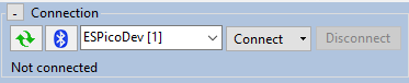
PSTrace version 5.6 or higher has a hidden feature that is useful when the communication protocol is used for development of software for the EmStat4. PSTrace will open the Connection viewer window when you double-click on the "Not connected" label before connecting to the device.
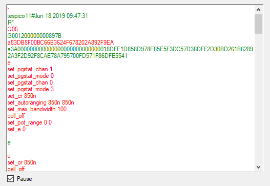
Once connected, the connection viewer window will show all messages transmitted to the instrument (in red), and messages received from the instrument (in green). This can be helpful to understand the communication between the host and the instrument. Below is an example of the connection viewer window. Note that PSTrace is connected to an EmStat Pico in this example.
2.2. Communication protocol
All commands and responses are terminated with a newline character.
The used newline character is the Line Feed (LF) character ('\n', ASCII code 10 or 0x0A).
The instrument never transmits a Carriage Return (CR) character ('\r', ASCII code 13 or 0x0D) and CR characters received by the instrument are ignored.
When a command is received by the instrument, it will echo the first character of the command and then respond with the command-specific data. After executing the command, a newline character is transmitted. If an error occurs during the execution of a command, the error is returned just before the newline character. See section Chapter 8, Error handling for more information about errors.
3. Command summary
The following table gives an overview of all communication protocol commands.
| ID | Command | Modes | Description |
|---|---|---|---|
0x01 |
All modes |
Get firmware version |
|
0x20 |
Idle |
Get runtime capabilities |
|
0x21 |
Idle |
Get MethodSCRIPT capabilities |
|
0x22 |
Idle |
Set register |
|
0x23 |
Idle |
Get register |
|
0x24 |
Idle |
Load MethodSCRIPT |
|
0x25 |
Idle |
Run loaded MethodSCRIPT |
|
0x26 |
Idle |
Execute (= load and run) MethodSCRIPT |
|
0x27 |
Idle |
Enter bootloader |
|
0x2B |
Idle |
Store loaded MethodSCRIPT to NVM |
|
0x2C |
Idle |
Load MethodSCRIPT from NVM |
|
0x30 |
Idle |
Get serial number |
|
0x31 |
Idle |
Get MethodSCRIPT version |
|
0x33 |
Idle |
Get directory listing |
|
0x34 |
Idle |
Read file |
|
0x35 |
Idle |
Write file |
|
0x36 |
Idle |
Delete file or directory |
|
0x37 |
Idle |
Get file system information |
|
0x38 |
Idle |
Format storage device |
|
0x39 |
Idle |
Mount file system |
|
0x3A |
Idle |
Unmount file system |
|
0x3B |
Idle |
Clear file system |
|
0x3C |
Idle |
Get multi-channel serial number |
|
0x3E |
Idle |
Load MethodSCRIPT from file |
|
0x3F |
Idle |
Execute (= load and run) MethodSCRIPT from file |
|
0x40 |
Idle |
Write file with cryptographic verification |
|
0x41 |
Idle |
Delete file with cryptographic verification |
|
0x42 |
Idle |
Format filesystem with cryptographic verification |
|
0x43 |
Idle |
Clear filesystem with cryptographic verification |
|
0x44 |
Idle |
Comm Lock |
|
0x45 |
Idle |
Comm Unlock |
|
0x60 |
Script |
Halt script execution |
|
0x61 |
Script |
Resume script execution |
|
0x62 |
Script |
Abort script execution |
|
0x63 |
Script |
Abort measurement loop |
|
0x65 |
Script |
Reverse CV sweep |
4. Command details
A list of all commands is given in the previous chapter. In this chapter, each commmand is described in more detail.
Some commands have one or more arguments. The format and meaning of such arguments is documented in those sections as well.
Commands are case-sensitive.
For example, s (hibernate) is a different command than S (Set register).
|
4.1. Get firmware version (t)
Get the device firmware version. This includes the device type, firmware version, build date and release type.
Command format
tResponse format
Unlike most other commands, this command has a response consisting of multiple lines.
The last line is terminated with an asterisk and a newline character ('*\n').
The format is as follows:
tddddddvv..vv#mmm dd yyyy hh:mm:ss
R*| Key | Type | Size | Description |
|---|---|---|---|
|
text |
6 |
The device type.
For the EmStat4 HR this is |
|
text |
20 |
The build date and time. |
|
text |
1 |
The release type: |
|
text |
1 |
Marks the end of the response. |
Example
Below are some examples to demonstrate the format of the output.
tes4_lr1000#Jun  7 2021 16:51:38
R*tes4_hr1100#Jan 28 2022 11:04:43
R*4.2. Set register (S)
Sets the value of a register. Registers contain instrument specific configuration, settings and information that are accessible to the user. See Chapter 6, Register details for more information.
Some registers require a specific permission level to be accessed.
See Section 6.2, “Permission level (0x02)” for more details.
|
Command format
Sxxyy...yy| Key | Type | Size | Description |
|---|---|---|---|
|
hex |
2 |
Register identifier (see Chapter 6, Register details) |
|
hex |
variable |
Value to write to the register, the number of digits depend on the register. |
Response format
SExample
The following example demonstrates writing the value 0xABCDEF12 to register 0x99 (= 153 decimal).
S99ABCDEF12S4.3. Get register (G)
Gets the value of a register. Registers contain instrument specific configuration, settings and information that are accessible to the user. See Chapter 6, Register details for more information.
Some registers require a specific permission level to be accessed.
See Section 6.2, “Permission level (0x02)” for more details.
|
Command format
Gxx| Key | Type | Size | Description |
|---|---|---|---|
|
hex |
2 |
Register identifier (see Chapter 6, Register details) |
Response format
Gyy...yy| Key | Type | Size | Description |
|---|---|---|---|
|
hex |
variable |
The value of the register when queried, the number of bytes depends on the register (see Chapter 6, Register details). |
Example
The following example demonstrates how to get the device serial (register 0x06) from the instrument.
G06G001200000000899B4.4. Load MethodSCRIPT (l)
Load a MethodSCRIPT into RAM.
The end of the script is indicated by an empty line (i.e., a line containing only the newline character \n).
The MethodSCRIPT is parsed during reception.
Some script errors that can be detected during parsing, such as syntax errors, are reported directly.
If an error is encountered during parsing, the script memory is cleared, so a new script must be loaded.
If the script was loaded successfully (no error was returned during loading), then the script can be executed by the r command (see Section 4.5, “Run loaded MethodSCRIPT (r)”).
Command format
This command consists of multiple lines.
The first line contains only the l command.
Then, the MethodSCRIPT is transmitted, line by line.
After the last MethodSCRIPT line, an empty line must be transmitted to end the command.
l
mm
..
mm| Key | Type | Size | Description |
|---|---|---|---|
|
text |
variable |
The MethodSCRIPT to load, terminated with an empty line. See the MethodSCRIPT documentation for more information. |
Response format
lExample
The following example loads a MethodSCRIPT that prints "Hello World" 5 times when executed.
It can then be executed with the run command, see Section 4.5, “Run loaded MethodSCRIPT (r)”,
l\n
var i\n
store_var i 0i ja\n
loop i < 3i\n
send_string "Hello World"\n
add_var i 1i\n
endloop\n
\nl\n4.5. Run loaded MethodSCRIPT (r)
Run (execute) loaded MethodSCRIPT from RAM.
Command format
rResponse format
The output of this command starts with r\n to denote the successful start of the script.
This response is then followed by the output of the MethodSCRIPT, which depends on the actual script that is running.
See the MethodSCRIPT documentation to see what type of responses can be expected.
Note that a MethodSCRIPT does not have to transmit data, but most scripts do.
When the MethodSCRIPT is finished (either successfully or with an error), an empty line is transmitted.
Summarized, the output format is:
r
pp..pp
...
pp..pp| Key | Type | Size | Description |
|---|---|---|---|
|
text |
variable |
The MethodSCRIPT output. See the MethodSCRIPT documentation for more information. |
Example
The following demonstrates running the MethodSCRIPT loaded in the example from Section 4.5, “Run loaded MethodSCRIPT (r)”.
rr
L
THello World
THello World
THello World
+
L and + are MethodSCRIPT hints about entering and leaving a loop.
|
4.6. Execute (= load and run) MethodSCRIPT (e)
Load and run a MethodSCRIPT (same as l followed by r ).
Command format
e
mm
..
mm| Key | Type | Size | Description |
|---|---|---|---|
|
text |
variable |
The MethodSCRIPT to load, terminated with an empty line. See the MethodSCRIPT documentation for more information. |
Response format
e
pp..pp
...
pp..pp| Key | Type | Size | Description |
|---|---|---|---|
|
text |
variable |
The MethodSCRIPT output. See the MethodSCRIPT documentation for more information. |
Example
The following demonstrates loading and running the same MethodSCRIPT as used in the example from Section 4.5, “Run loaded MethodSCRIPT (r)”.
e
var i
store_var i 0i ja
loop i < 3i
send_string "Hello World"
add_var i 1i
endloope
L
THello World
THello World
THello World
+4.7. Load MethodSCRIPT from file (l_fs)
Load a MethodSCRIPT stored on the filesystem into RAM.
The end of the script is indicated by an empty line (i.e., a line containing only the newline character \n).
Some script errors that can be detected during parsing, such as syntax errors, are reported directly.
If an error is encountered during parsing, the script memory is cleared, so a new script must be loaded.
If the script was loaded successfully (no error was returned during loading), then the script can be executed by the r command (see Section 4.5, “Run loaded MethodSCRIPT (r)”).
Command format
l_fs filename| Key | Type | Size | Description |
|---|---|---|---|
|
text |
variable |
The path of the MethodSCRIPT on the filesystem |
Response format
lExample
The following example loads a MethodSCRIPT from a file named scripts/my_script.
If the script is loaded successfully, a subsequent r command would run it.
l_fs scripts/my_scriptl4.8. Execute (= load and run) MethodSCRIPT from file (e_fs)
Load and run a MethodSCRIPT from the filesystem (same as l_fs followed by r ).
Command format
e_fs filename| Key | Type | Size | Description |
|---|---|---|---|
|
text |
variable |
The path of the MethodSCRIPT on the filesystem |
Response format
e
pp..pp
...
pp..pp| Key | Type | Size | Description |
|---|---|---|---|
|
text |
variable |
The MethodSCRIPT output. See the MethodSCRIPT documentation for more information. |
Example
The following example loads and runs a MethodSCRIPT from a file named scripts/my_script.
For this example, we presume that scripts/my_script contains the following:
var i\n
store_var i 0i ja\n
loop i < 3i\n
send_string "Hello World"\n
add_var i 1i\n
endloop\n
\ne_fs scripts/my_scripte
L
THello World
THello World
THello World
+4.9. Store loaded MethodSCRIPT to NVM (Fmscr)
Store a loaded MethodSCRIPT to non-volatile memory (NVM).
Command format
FmscrResponse format
FExample
The following example demonstrates loading a script with l and storing it into the instrument’s non-volatile memory.
l
send_string "Hello World!"

Fmscrl
F4.10. Load MethodSCRIPT from NVM (Lmscr)
Load a MethodSCRIPT from non-volatile memory (NVM).
After the script has been loaded successfully, it can be executed by the r command (see Section 4.5, “Run loaded MethodSCRIPT (r)”).
A MethodSCRIPT can only be loaded from NVM if it was written using the same MethodSCRIPT version as the current firmware supports.
Command format
LmscrResponse format
LExample
This example shows how to load a script from non-volatile memory (NVM) and execute it with an r command.
The loaded script here was loaded in the example from Section 4.10, “Load MethodSCRIPT from NVM (Lmscr)”
Lmscr
rL
r
THello World!4.11. Get serial number (i)
Get the serial number of the instrument.
| For some instruments, this is not the same as the serial printed on the housing. |
Command format
iResponse format
ixx..xx| Key | Type | Size | Description |
|---|---|---|---|
|
text |
variable |
The serial number. |
Example
The following example queries the device serial.
iiES4LR21E03994.12. Get multi-channel serial number (m)
Get the device serial number from a multi-channel instrument.
Some instruments, such as the MultiEmStat4, consist of multiple devices internally, each with their own communication interface.
In this case, each device will return a different serial number using the i command.
However, the m command will return the same serial number on each connection, which is the serial number of the combined (multi-channel) instrument.
The multi-channel serial number also contains the channel number (which is different for each instrument inside the multi-instrument) and the total number of channels.
This allows the host software to determine if all channels are connected.
If the instrument is not in a multi-channel configuration, this will throw an error instead.
Command format
mResponse format
mss..ssCHiii-nnn| Key | Type | Size | Description |
|---|---|---|---|
|
text |
variable |
The multi-channel serial number. |
|
text |
2 |
A fixed delimiter. |
|
dec |
3 |
Channel number (1..N). |
|
dec |
3 |
Total number of channels (N). |
Example
The following example queries the multi-channel serial.
mmMES4HR2106000310CH010-0124.13. Get MethodSCRIPT version (v)
Get the MethodSCRIPT version.
This number indicates the internal storage representation of a MethodSCRIPT rather than the version of MethodSCRIPT specification.
The MethodSCRIPT version number is used to determine if the MethodSCRIPT stored in NVM (using the Fmscr command) can be loaded or not.
A list of EmStat4 firmware versions and the associated MethodSCRIPT versions is given below.
| EmStat4 firmware version | MethodSCRIPT version |
|---|---|
1.0.00 |
0003 |
1.1.00 |
0006 |
1.2.00 |
01.04.00 |
1.3.00 |
01.05.00 |
1.4.03 |
01.07.01 |
1.4.04 |
01.08.00 |
1.5.00 |
01.09.00 |
Command format
vResponse format
vxx..xx| Key | Type | Size | Description |
|---|---|---|---|
|
text |
variable |
The MethodSCRIPT version supported by the firmware. |
Example
This example demonstrates reading the MethodSCRIPT version.
vv01.06.004.14. Enter bootloader (dlfw)
Resets the instrument into bootloader mode. The bootloader is mainly intended to perform firmware updates.
Command format
dlfwResponse format
d4.15. Get directory listing (fs_dir)
Get a list of all files in the specified directory.
| It might take some time to find all files on the file system. |
On EmStat4 and EmStatPico based devices fs_dir recursively shows files in subdirectories.
On the Nexus, only the immediate directory contents are shown.
|
Command format
fs_dir [path]| Key | Type | Size | Description |
|---|---|---|---|
|
text |
variable |
(Optional) Path of the directory to search. If no path is provided, all files on the file system are included. |
Response format
The response will consist of one line of information for each file found. The information includes the file date and time, type (directory or normal file), size, and path. The response ends with an empty line.
f
YYYY-MM-DD hh-mm-ss;TTT;SS..SS;pp..pp
...
YYYY-MM-DD hh-mm-ss;TTT;SS..SS;pp..pp| Key | Type | Size | Description |
|---|---|---|---|
|
dec |
4* |
File date†, year |
|
dec |
2* |
File date†, month (01-12) |
|
dec |
2* |
File date†, day (01-31) |
|
dec |
2* |
File time†, hours (00-23) |
|
dec |
2* |
File time†, minutes (00-59) |
|
dec |
2* |
File time†, seconds (00-59) |
|
text |
3 |
File type ( |
|
dec |
variable (1-10) |
File size in bytes |
|
text |
variable |
Path to the file/directory |
* Older firmware versions may print the decimal fields without padding, e.g:0-0-0 0-0-0;FIL;0;empty.txt
|
| † The file date and time are based on the system date and time. In order to have a meaningful file date/time, make sure to set the system date and time before creating a file. |
| Depending on the device, the timestamp associated with a file may be its creation time or its last modification time. On the EmStatPico, Sensit Wearable, and EmStat4, it is the creation time. On the Nexus, it is the last modification time. |
| In case a file is not closed correctly, the file size will be reported as 4294967295 bytes. This can happen if an instrument is powered down while a file was still open. In this case, a small amount of data that was not flushed to the file storage yet might be lost. However, the file should still be readable, and the correct amount of data (that has been successfully written) will be returned. |
Example
The following example lists the content of the example/doc directory.
fs_dir example/doc/f
2022-02-22 20:22:02;FIL;4;example/doc/test.txt
2022-02-22 22:22:22;FIL;14;example/doc/measurement.txtf4.16. Read file (fs_get)
Read a file from the file system on the instrument.
Command format
fs_get <path>| Key | Type | Size | Description |
|---|---|---|---|
|
text |
variable |
Path of the file to retrieve. |
Response format
The command fs_get <path>\n prints f\n, followed by the contents of the requested file.
The end of the file is indicated by an ASCII file separator character (0x1C).
The output ends with an empty line (i.e., a newline character) if the file was read and transmitted successfully, otherwise it ends with an error code.
The file separator character is always transmitted, even in case of a file error.
f
cc..cc
cc..cc
cc..cc
\x1C| Key | Type | Size | Description |
|---|---|---|---|
|
text |
variable |
The file content in ASCII format. |
|
- |
1 |
The file separator character ( |
Example
This example requests the contents of the file example/hello_world.txt.
fs_get example/hello_world.txtf
This is an example. Hello World!
The next line contains an file separator indicating end of transfer.
\x1C4.17. Write file (fs_put)
Write a file to the file system of the instrument. The file path must be unique. If a file with the same path already exists, an error is returned.
Command format
The command starts with fs_put <path>\n, where path is the path of the file to write.
The following lines are the file contents, that are written to the file.
The end of the file is indicated by an ASCII file separator character (0x1C).
fs_put <path>
xx..xx
\x1C| Key | Type | Size | Description |
|---|---|---|---|
|
text |
variable |
The file path. |
|
text |
variable |
The file content in ASCII format. |
|
- |
1 |
The file separator character ( |
Response format
The command returns a \n when it is accepted, as all commands do.
It also returns an additional empty line (\n) when the command is finished.
fExample
fs_put example/hello_world.txt
This is an example. Hello World!
The next line contains a file separator indicating end of transfer.
\x1Cf4.18. Delete file or directory (fs_del)
Remove a file or directory (recursively) from the file system.
| This can take a long time for file trees containing many elements. |
Command format
fs_del <path>| Key | Type | Size | Description |
|---|---|---|---|
|
text |
variable |
Path of the file or directory to remove. |
Response format
fExample
The following example removes the file /log.txt.
fs_del /log.txtf4.19. Get file system information (fs_info)
Get information about the file system (free/used/total space).
The file system information consists of free space, used space and total space.
| Due to file system overhead, the total space will be less than the nominal capacity of the storage medium. Because files are allocated in blocks the actual size of the file will always be a multiple of this block size. For example, by writing 100 bytes to a file, the used space could increase with 8 kB, and the free size decrease accordingly. |
Command format
fs_infoResponse format
f
used:UU..UUkB free:FF..FFkB total:TT..TTkB| Key | Type | Size | Description |
|---|---|---|---|
|
dec |
variable |
Used size in kB* |
|
dec |
variable |
Free size in kB* |
|
dec |
variable |
Total size in kB* |
* 1 kB = 1024 bytes
Example
fs_infoused:192kB free:7878464kB total:7878656kB4.20. Format storage device (fs_format)
Format the file storage medium. This prepares the storage medium to be used as file system. It also removes all existing data.
Formatting a (large) storage device can take some time.
Once the storage device is formatted, it is generally not necessary to use this command again.
To only remove all files, it is recommended to use the fs_clear command instead.
The fs_clear command is usually much faster than the fs_format command.
| Formatting the file storage erases all files. This operation cannot be undone. |
Command format
fs_formatResponse format
f4.22. Unmount file system (fs_unmount)
Unmount the file system.
This can be used to re-mount the filesystem, in combination with fs_mount.
Command format
fs_unmountResponse format
f4.23. Clear file system (fs_clear)
Remove all files and folders from the storage medium.
| This operation cannot be undone. |
Command format
fs_clearResponse format
f4.24. Get runtime capabilities (CC)
Get the runtime capabilities. Return a list of supported commands for the instrument. Each bit represent one command, the mapping between bits and commands can be found in Appendix C, Communication capabilities bit fields.
Command format
CCResponse format
CXXXXXXXXXXXXXXXXXXXXXXXXXXXXXXXXXXXXXXXXXXXXXXXXXXXXXXXXXXXXXXXX| Key | Type | Size | Description |
|---|---|---|---|
|
hex |
32 |
Bit fields for commands |
Example
CCC000000000000000000000000000000000000000F000000001FFFD8FF0000000E4.25. Get MethodSCRIPT capabilities (CM)
Get the MethodSCRIPT capabilities. Return a list of MethodSCRIPT commands that are licensed and supported by the instrument, as hexadecimal value. Each bit represent one command, the mapping between bits and commands can be found in Appendix B, MethodSCRIPT capabilities bit fields
Command format
CMResponse format
CYYYYYYYYYYYYYYYYYYYYYYYYYYYYYYYYYYYYYYYYYYYYYYYYYYYYYYYYYYYYYYYY| Key | Type | Size | Description |
|---|---|---|---|
|
hex |
32 |
Bit fields for MethodSCRIPT commands |
Example
CMC000000000000000000000000000000000000000002BFFF87FFFFFFFFFFBFFFFE4.26. Halt script execution (h)
Halt execution of the running MethodSCRIPT.
This "pauses" the script.
Execution can be resumed using the H command (see Section 4.27, “Resume script execution (H)”).
Command format
hResponse format
hExample
See the examples in Section 4.29.
4.27. Resume script execution (H)
Resume execution of the halted MethodSCRIPT.
Command format
HResponse format
HExample
See the examples in Section 4.29.
4.28. Abort script execution (Z)
Abort execution of the current MethodSCRIPT.
This has the same effect as the MethodSCRIPT command abort.
It effectively stops the execution of the script as soon as possible.
If an abort occurs during a (measurement) loop, all endloop commands are still executed.
Consequently, the * and + characters that denote the end of a loop will still be transmitted.
If the MethodSCRIPT contains an on_finished: tag, the commands after it will still be executed.
MethodSCRIPT commands after the on_finished: tag cannot be aborted.
Unlike the MethodSCRIPT command abort, the command can also abort some long-running MethodSCRIPT commands, such as await_int and certain measurements.
Command format
ZResponse format
ZExample
See the examples in Section 4.29.
4.29. Abort measurement loop (Y)
Abort the current measurement loop.
This will break the execution of a MethodSCRIPT measurement loop command (i.e., a command starting with meas_loop_) after the current iteration.
The current measurement iteration, i.e., all MethodSCRIPT commands between the start and the end of the measurement loop, will be executed, but no new iteration will be started.
The script will then continue execution after the endloop command.
Command format
YResponse format
YExample
Below is an example MethodSCRIPT that performs a linear sweep from -1 V to +1 V, with steps of 250 mV and a scan rate of 100 mV/s. This results in 9 measurements, each 2.5 second apart, with a total runtime of approximately 22.5 seconds. In our example setup, a 100 kΩ resistor was connected to the working electrode, so the measured current is expected to be between -10 µA and +10 µA, and the current range is set accordingly.
var c
var p
var i
var t
store_var i 0i ja
set_pgstat_mode 2
set_range ba 10u
cell_on
timer_start
meas_loop_lsv p c -1 1 250m 100m
add_var i 1i
pck_start
pck_add i
pck_add p
pck_add c
pck_end
endloop
timer_get t
meas 100m c ba
pck_start
pck_add t
pck_add c
pck_end
on_finished:
cell_off
send_string "Finished"
When the program is executed completely, the output will be something like this:
e
M0000
Pja8000001i;da7F0BDF9u;ba7678CD7p,10,20F,40
Pja8000002i;da7F48ED6u;ba78DBCE5p,10,20F,40
Pja8000003i;da7F85FB4u;ba7B3E948p,10,20F,40
Pja8000004i;da7FC3092u;ba7DA1200p,10,20F,40
Pja8000005i;da8059967n;ba8D7055Ef,14,20F,40
Pja8000006i;da803D24Cu;ba8265C17p,10,20F,40
Pja8000007i;da807A32Au;ba84C8C26p,10,20F,40
Pja8000008i;da80B7408u;ba872B4DDp,10,20F,40
Pja8000009i;da80F44E5u;ba898E141p,10,20F,40
*
Peb9570C36u;ba898E141p,10,20F,40
TFinished
The values in the data packages indicate that the measurement loop took approximately 22.5 seconds, and that the measured current after the measurement loop has the same value as during the last iteration of the loop.
However, if a Y command is send after the second iteration, the output will be something like this:
e
M0000
Pja8000001i;da7F0BDF9u;ba7679082p,10,20F,40
Pja8000002i;da7F48ED6u;ba78DB93Ap,10,20F,40
Y
Pja8000003i;da7F85FB4u;ba7B3E1F1p,10,20F,40
*
Peb872184Au;ba7D9E9A2p,10,20F,41
TFinished…or, depending on the exact time the Y command is received, like this:
e
M0000
Pja8000001i;da7F0BDF9u;ba767942Ep,10,20F,40
Pja8000002i;da7F48ED6u;ba78DC43Cp,10,20F,40
Y
*
Peb84D7686u;ba7B3E948p,10,20F,40
TFinished
In this case, the values indicate that the measurement loop only took 5 seconds, and that the WE potential remained at the value it had at the end of the last iteration that was executed.
By halting the program after the second iteration, the output would be:
e
M0000
Pja8000001i;da7F0BDF9u;ba767942Ep,10,20F,40
Pja8000002i;da7F48ED6u;ba78DB93Ap,10,20F,40
h
If the program would now be continued and then aborted after three more iterations, the output would be:
H
Pja8000003i;da7F85FB4u;ba7B3E59Dp,11,20F,40
Pja8000004i;da7FC3092u;ba7DA0E54p,10,20F,40
Pja8000005i;da8059967n;ba8C8AFADf,14,20F,40
Z
*
TFinished
As can be seen in the above example, the metadata of the 3th iteration (the value 11) indicates that a timing error occurred.
It can also be seen that the code directly following the measurement loop is not executed when the script is aborted using the Z command, in contrast to the Y command, which only aborts the measurement loop but continues executing the remainder of the MethodSCRIPT.
4.30. Reverse CV sweep (R)
During a CV (but not fast CV) sweep, reverse the sweep direction.
This has the same effect as the MethodSCRIPT command set_scan_dir 0.
Depending on the exact location where the reversal occurs, this may end the current scan early and advance to the next, if present.
This command has no effect if run outside of a CV sweep.
Command format
RResponse format
RExample
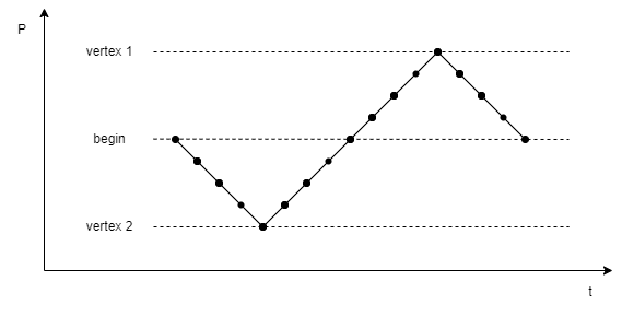
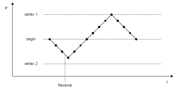
The plots below show the behaviour of the CV reverse command.
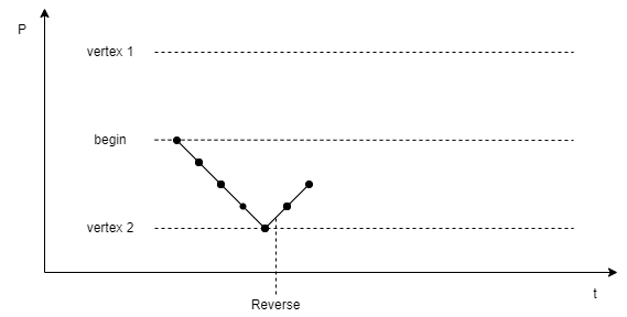
The following MethodSCRIPT examples demonstrate the same behaviour.
This script performs a 3 vertex CV measurement, from 0 V to -1 V to 1 V, with steps of 250 mV and a scan rate of 1 V/s. Here only the potentials are sent back, for simplicity.
e
var c
var p
set_pgstat_chan 0
set_pgstat_mode 2
set_max_bandwidth 40
set_range ba 2100u
set_autoranging ba 210n 21m
set_e 0
cell_on
meas_loop_cv p c 0 -1 1 250m 1
pck_start
pck_add p
pck_end
endloop
on_finished:
cell_off
This results in 17 points.
e
M0005
Pda8000000
Pda7FC2F23u
Pda7F85E45u
Pda7F48D67u
Pda7F0BC8Au
Pda7F48D67u
Pda7F85E45u
Pda7FC2F23u
Pda8000000
Pda803D0DDu
Pda807A1BBu
Pda80B7299u
Pda80F4376u
Pda80B7299u
Pda807A1BBu
Pda803D0DDu
Pda8000000
*
Issuing the reverse command causes the sweep to change direction early. Below it can be seen that the sweep only performs 3 steps in its initial direction instead of 4.
It can be seen that there is a delay between the R command being echo’d, and the data reversing.
This occurs due to the sweep potentials being set in advance, and so it shouldn’t be expected that the R command will take immediate effect.
e
M0005
Pda8000000
Pda7FC2F23u
Pda7F85E45u
R
Pda7F48D67u
Pda7F85E45u <--- Previously this was another step down to Pda7F0BC8Au
Pda7FC2F23u
Pda8000000
Pda803D0DDu
Pda807A1BBu
Pda80B7299u
Pda80F4376u
Pda80B7299u
Pda807A1BBu
Pda803D0DDu
Pda8000000
*
If the reversal would cause the sweep to change to a potential and direction that do not appear later in the current scan, then the sweep will advance to the next scan. If the CV is already in the final scan, it will end the CV instead. This can be seen in the below data.
e
M0005
Pda8000000
Pda7FC2F23u
Pda7F85E45u
Pda7F48D67u
Pda7F0BC8Au
R
Pda7F48D67u
Pda7F85E45u
*
4.31. Write file with cryptographic verification (sfs_put)
Has the same behaviour as Section 4.17, “Write file (fs_put)”.
The data is accompanied by a cryptographic tag which proves it is authorised.
To use this feature, a shared key must have been configured.
See Section 6.25, “User Encryption Key (0x8A)” for further information on this key.
Command format
The command looks as follows:
sfs_put <cryptographic mac> <payload length> <filename>
| Key | Type | Size | Description |
|---|---|---|---|
|
text |
variable |
The hexadecimal, 16B MAC of the command payload |
|
text |
variable |
The length of the filename, plus the length of the file to be sent |
|
text |
variable |
The location to store the file to |
The cryptographic MAC used is the CBC-MAC within AES-CCM, with nonce 0, and using the Section 6.25, “User Encryption Key (0x8A)” as the key.
To retrieve the MAC, a user may perform CCM encryption and discard the ciphertext.
The plaintext input to the encryption is:
-
The literal bytes
sfs_put -
The
payload_lengthfield (4B little endian) -
The filename
-
The file contents.
Example
This is an example sfs_put transaction to write a file named my_file.txt.
The encrypted values assume a key of 0x00112233445566778899aabbccddeeff and unique instrument ID 0XAABBAABBAABBAABBAABBAABB.
Note that the final line, \x1C, represents the file separator character that ends a file write operation.
sfs_put 89177e73162fb9eb7901fe6d731827f4 24000000 test_sfs_put
Hello World
Second Line
\x1Cs4.32. Delete file with cryptographic verification (sfs_del)
Has the same behaviour as Section 4.18, “Delete file or directory (fs_del)”.
The data is accompanied by a cryptographic tag which proves it is authorised.
To use this feature, a shared key must have been configured.
See Section 6.25, “User Encryption Key (0x8A)” for further information on this key.
Command format
The command looks as follows:
sfs_del <cryptographic mac> <filename>
| Key | Type | Size | Description |
|---|---|---|---|
|
text |
variable |
The hexadecimal, 16B MAC of the command payload |
|
text |
variable |
The location to store the file to |
The cryptographic MAC used is the CBC-MAC within AES-CCM, with nonce 0, and using the Section 6.25, “User Encryption Key (0x8A)” as the key.
To retrieve the MAC, a user may perform CCM encryption and discard the ciphertext.
The plaintext input to the encryption is:
-
The literal bytes
sfs_del -
The length of filename (4B little endian)
-
The filename
Example
This is an example sfs_del transaction to delete a file named my_file.txt.
The encrypted values assume a key of 0x00112233445566778899aabbccddeeff and unique instrument ID 0XAABBAABBAABBAABBAABBAABB.
sfs_del 8e7b4d5d7cfcc300028396df839fb400 test_sfs_dels4.33. Clear filesystem with cryptographic verification (sfs_clear)
Has the same behaviour as Section 4.23, “Clear file system (fs_clear)”.
The data is accompanied by a cryptographic tag which proves it is authorised.
To use this feature, a shared key must have been configured.
See Section 6.25, “User Encryption Key (0x8A)” for further information on this key.
Command format
The command looks as follows:
sfs_clear <cryptographic mac>
| Key | Type | Size | Description |
|---|---|---|---|
|
text |
variable |
The hexadecimal, 16B MAC of the command payload |
The cryptographic MAC used is the CBC-MAC within AES-CCM, with nonce 0, and using the Section 6.25, “User Encryption Key (0x8A)” as the key.
To retrieve the MAC, a user may perform CCM encryption and discard the ciphertext.
The plaintext input to the encryption is:
-
The literal bytes
sfs_clear
If this command is replayed at a later time, a malicious actor could clear the filesystem at will.
If this is unacceptable, consider deleting individual files with sfs_del.
|
Example
This is an example sfs_clear transaction.
The encrypted values assume a key of 0x00112233445566778899aabbccddeeff and unique instrument ID 0XAABBAABBAABBAABBAABBAABB.
sfs_clear 7149a3478cc7c47d5d37d021c80bd02ds4.34. Format filesystem with cryptographic verification (sfs_format)
Has the same behaviour as Section 4.20, “Format storage device (fs_format)”.
The data is accompanied by a cryptographic tag which proves it is authorised.
To use this feature, a shared key must have been configured.
See Section 6.25, “User Encryption Key (0x8A)” for further information on this key.
Command format
The command looks as follows:
sfs_format <cryptographic mac>
| Key | Type | Size | Description |
|---|---|---|---|
|
text |
variable |
The hexadecimal, 16B MAC of the command payload |
The cryptographic MAC used is the CBC-MAC within AES-CCM, with nonce 0, and using the Section 6.25, “User Encryption Key (0x8A)” as the key.
To retrieve the MAC, a user may perform CCM encryption and discard the ciphertext.
The plaintext input to the encryption is:
-
The literal bytes
sfs_format
If this command is replayed at a later time, a malicious actor could format the filesystem at will.
If this is unacceptable, consider deleting individual files with sfs_del.
|
Example
This is an example sfs_format transaction.
The encrypted values assume a key of 0x00112233445566778899aabbccddeeff and unique instrument ID 0XAABBAABBAABBAABBAABBAABB.
sfs_format d51c894224267c6667bb1990d8ef10c1s4.35. Comm Lock (comm_lock)
Reconfigure the device to reject all comm commands that would modify the device.
The exception is the secure filesystem (sfs) commands, which are still permitted.
To use this feature, a shared key must have been configured.
See Section 6.25, “User Encryption Key (0x8A)” for further information on this key.
| Locking only takes effect when the device is resetted. In devices with the NVM commit register, the NVM must also be committed. |
Command format
The command looks as follows:
comm_lock <cryptographic mac>
| Key | Type | Size | Description |
|---|---|---|---|
|
text |
variable |
The hexadecimal, 16B MAC (32 ascii characters) |
The cryptographic MAC used is the CBC-MAC within AES-CCM, with nonce 0, and using the Section 6.25, “User Encryption Key (0x8A)” as the key.
To retrieve the MAC, a user may perform CCM encryption and discard the ciphertext.
The plaintext input to the encryption is:
-
The literal bytes
comm_lock
Example
The encrypted values assume a key of 0x00112233445566778899aabbccddeeff and unique instrument ID 0XAABBAABBAABBAABBAABBAABB.
comm_lock 981D3C21C07FCA7248916D636EA9B1D3c4.36. Comm Unlock (comm_unlock)
Reconfigure the device to accept all comm commands that would modify the device.
To use this feature, a shared key must have been configured.
See Section 6.25, “User Encryption Key (0x8A)” for further information on this key.
| Unlocking takes effect immediately, but in devices with the NVM commit register, the NVM must be committed for the setting to persist. |
Command format
The command looks as follows:
comm_unlock <cryptographic mac>
| Key | Type | Size | Description |
|---|---|---|---|
|
text |
variable |
The hexadecimal, 16B MAC (32 ascii characters) |
The cryptographic MAC used is the CBC-MAC within AES-CCM, with nonce 0, and using the Section 6.25, “User Encryption Key (0x8A)” as the key.
To retrieve the MAC, a user may perform CCM encryption and discard the ciphertext.
The plaintext input to the encryption is:
-
The literal bytes
comm_unlock
Example
The encrypted values assume a key of 0x00112233445566778899aabbccddeeff and unique instrument ID 0XAABBAABBAABBAABBAABBAABB.
comm_unlock 3CF68483D0B3D545A44CE38CAE7A48C1c5. Register summary
5.1. Generic registers
The following table defines registers that are the same on all MethodSCRIPT instruments.
| ID | Description | Length (bytes) | Basic permission | Advanced permission |
|---|---|---|---|---|
0x01 |
4 |
Read only |
Read / write |
|
0x02 |
4 |
Write only |
Write only |
|
0x04 |
8 |
Read only |
Read only |
|
0x05 |
16 |
Read only |
Read only |
|
0x06 |
8 |
Read only |
Read only |
|
0x08 |
1 |
Read only |
Read / write |
|
0x09 |
4 |
Read only |
Read / write |
|
0x0A |
4 |
Read / write |
Read / write |
|
0x0B |
4 |
Write only |
Write only |
|
0x0D |
1 |
Read only |
Read / write |
|
0x0E |
7 |
Read / write |
Read / write |
|
0x0F |
8 |
Read only |
Read / write |
|
0x10 |
4 |
Read only |
Read only |
|
0x11 |
8 |
Read only |
Read only |
|
0x12 |
1 |
Read only |
Read / write |
|
0x13 |
1 |
Read only |
Read / write |
|
0x14 |
1 |
Read only |
Read / write |
|
0x15 |
1 |
Read only |
Read / write |
|
0x16 |
1 |
Read only |
Read / write |
|
0x17 |
1 |
Read only |
Read / write |
5.2. EmStat4 specific registers
The table below lists all registers that are specific to the EmStat4.
| ID | Description | Length (bytes) | Basic permission | Advanced permission |
|---|---|---|---|---|
0x81 |
4 |
None |
Write only |
|
0x87 |
8 |
Read only |
Read only |
|
0x88 |
2 |
Read only |
Read / write |
|
0x89 |
1 |
Read only |
Read / write |
|
0x8A |
16 |
Read only |
Read / write |
|
0x8C |
4 |
Read only |
Read / write |
|
0x8D |
1 |
Read only |
Read / write |
6. Register details
The internal registers are used to retrieve information, configure the instrument, or perform rarely used actions.
Some registers are write protected at startup and must be unlocked before use.
The tables in Chapter 5, Register summary show which access rights each register has for each permission level.
The Permission level (0x02) register can be used to set the permission level.
The data length of each register is given in bytes of represented data. This data is communicated in hexadecimal notation, using 2 characters per byte.
Some registers are stored in the non-volatile memory (NVM) of the instrument, meaning that the setting can be remembered even after a power cycle.
6.1. Peripheral configuration (0x01)
Reads / writes the peripheral configuration as a bitmask from / to non-volatile memory. Support for external peripherals can be enabled here. Pins for peripherals that are not enabled can be used as GPIO pins. All peripherals default to GPIO. Multiple peripherals can be enabled at the same time by adding the hexadecimal values. For example: bit 1 is 0x01 and bit 5 is 0x20, combining them gives 0x21.
| This setting is stored in NVM. |
Register format
xxxxxxxx| Key | Size (bytes) | Description |
|---|---|---|
|
4 |
Peripheral configuration flags. |
| Mask | Name | Description |
|---|---|---|
0x0001 |
Disable power LED |
Disable the (blue) power LED. |
0x0040 |
Use external cell LED |
When enabled, output the cell ON/OFF status on GPIO2 instead of the internal cell LED. The signal is active-high: Cell ON outputs a logic 1, cell OFF output a logic 0. GPIO2 can not be used for other purposes if this option is enabled. |
Other |
Reserved |
Reserved for future use. Do not change! |
6.2. Permission level (0x02)
By default, most registers are write protected to prevent accidental writes. This register can be used to disable the write protection. It is advised to turn the write protection back on when access to write protected registers is no longer required.
Register format
kkkkkkkk| Key | Size (bytes) | Description |
|---|---|---|
|
4 |
Key to for switching to a specific permission mode. See Table 3, “Permission keys”. |
| Level | Key | Description |
|---|---|---|
Basic |
0x12345678 |
Default configuration at startup. Read-only access to non-volatile registers. |
Advanced |
0x52243DF8 |
Full access to all user changeable settings. |
6.3. License register (0x04)
Request the licenses programmed into this instrument. For more information contact PalmSens.
Register format
xxxxxxxxxxxxxxxx| Key | Size (bytes) | Description |
|---|---|---|
|
8 |
Instrument specific license key. |
Example
G046.4. Unique instrument ID (0x05)
Reads the unique ID for this instrument.
| This is different than the device serial number. |
Register format
xxxxxxxxxxxxxxxxxxxxxxxxxxxxxxxx| Key | Size (bytes) | Description |
|---|---|---|
|
16 |
Unique hardware identifier. |
Example
G056.5. Device serial number (0x06)
Contains the device serial number.
Register format
ttyybbbbnnnnnnnn| Key | Size (bytes) | Description |
|---|---|---|
|
1 |
A number specifying the device type. |
|
1 |
Production year. |
|
2 |
Production batch nr. |
|
4 |
Device ID, unique within all devices of the same type, year and batch. |
Example
G06G001200000000899B6.6. MethodSCRIPT autorun (0x08)
If set to 1, the MethodSCRIPT stored in non-volatile memory will be loaded and executed on startup. When the script ends, the EmStat4 returns to its normal behavior.
| This setting is stored in NVM. |
Register format
aa| Key | Size (bytes) | Description |
|---|---|---|
|
1 |
Autorun enable (00=disabled, 01=enabled). |
Example
G08S08016.7. Advanced options (0x09)
The advanced options register is a bitmask of advanced options that can be enabled by the user.
Each option has a specific bit value (see table below). The value of this register is a bitwise OR of all option flags that are enabled. Writing to this register sets or clears all bits to the specified value. When writing to this register, make sure to set all required bits at once.
| This setting is stored in NVM. |
| Bit mask | Description |
|---|---|
|
Enable CRC16 protocol extension. |
Register format
aaaaaaaa| Key | Size (bytes) | Description |
|---|---|---|
|
4 |
Advanced options |
Example
G09S0900000000
If the CRC16 protocol extension is (accidentally) enabled, it can only be disabled using a command including valid CRC.
In this case, the command S0900000000AA9D43 can be used to clear the advanced options register, including the CRC16 protocol extension.
|
6.8. UART data rate limit (0x0A)
This register allows limiting the number of bytes per second that are sent by the device using UART. This is independent of the UART baud rate. This can be useful when no flow control mechanism is used with UART and the host cannot keep up with the data rate defined by the baud rate. A value of 0 disables data rate limiting, so the instrument will transmit at the maximum achievable speed.
Register format
dddddddd| Key | Size (bytes) | Description |
|---|---|---|
|
4 |
Data rate limit in bytes per second |
Example
G0AS0A000013886.9. Reset instrument (0x0B)
Writing 0x93628ADE to this register will initiate a software reset of the device.
| This command will not return a newline if the reset is successful. |
Register format
93628ADE| Key | Size (bytes) | Description |
|---|---|---|
|
4 |
Magic key to reset the instrument. |
Example
S0B93628ADE6.10. Multi-channel role (0x0D)
Instrument role in a multi-channel setup.
When combining multiple instruments to create a multi-channel setup (as in, for example, the MultiEmStat4), it is sometimes necessary to synchronize all channels, so all measurements are performed at the same time.
This can be achieved using the MethodSCRIPT command set_channel_sync.
When using this feature, one instrument must be configured as master, and all others as slave.
The multi-channel role determines how the instrument behaves when synchronization commands are used.
When "hardware select" is selected, reading this register will return hardware select master (0x6D) or hardware select slave (0x73).
This role is assigned from the factory and depends on the physical layout.
Options are:
| Value | Description |
|---|---|
0x00 |
Standalone, no multi-instrument |
0x48 |
Hardware select |
0x4D |
Master |
0x53 |
Slave |
0x6D |
Hardware select master |
0x73 |
Hardware select slave |
0xFF |
RESERVED |
The hardware synchronisation role pin register must be configured before setting the Section 6.10, “Multi-channel role (0x0D)” register is set to hardware select.
|
Register format
mm| Key | Size (bytes) | Description |
|---|---|---|
|
1 |
Multi-instrument role |
6.11. System date and time (0x0E)
The system date and time in hex format.
This is used for the time/date shown on files in the file system and for the MethodSCRIPT command rtc_get.
Depending in the instrument, the time may or may not be kept on a restart.
Register format
yyyymmddhhaass| Key | Size (bytes) | Description |
|---|---|---|
|
2 |
Year, in HEX format |
|
1 |
Month (1-12), in HEX format |
|
1 |
Day (1-31), in HEX format |
|
1 |
Hour (0-23), in HEX format |
|
1 |
Minute (0-59), in HEX format |
|
1 |
Second (0-59), in HEX format |
6.12. Default GPIO config (0x0F)
Default GPIO settings at startup. Once set (and committed to NVM) the instrument will initialize it’s GPIO to this state on startup.
| This setting is stored in NVM. |
| The GPIO config is not checked when this register is updated. An incorrect configuration can cause a system warning during startup. |
Register format
ccccccccoooopppp| Key | Size (bytes) | Description |
|---|---|---|
|
4 |
GPIO configuration mode with 2 bits per pin. The values are: |
|
2 |
Output level with 1 bit per pin (only applicable for output pins) |
|
2 |
Pull-up enabled with 1 bit per pin (only applicable for input pins) |
Example
S0F00000004000200016.13. System warning (0x10)
Read and clear the system warning.
If a problem occurred that can not be displayed or handled at that moment, a system warning is set. This is indicated with the blinking LED and available in this register. Reading this register will return the first error code that caused a system warning. This is usually the most meaningful error code, since any subsequent errors might be a consequence of the first error. This register is cleared when read.
Register format
wwwwwwww| Key | Size (bytes) | Description |
|---|---|---|
|
4 |
Last encountered error code |
Example
G106.14. Allowed pin modes (0x11)
Get allowed pin modes (input / output / peripheral) for all GPIO pins.
The allowed modes depend on the instrument’s capabilities, NVM configuration and enabled features.
Some features may reserve specific GPIO pins, in that case they are not accessible via MethodSCRIPT and will read as 0.
Each nibble (4 bits) represents 1 GPIO pin, the least significant nibble is GPIO0.
Each bit within this nibble represents a pinmode, where a high bit means the mode is allowed.
bit 0: input
bit 1: output
bit 2: peripheral 1
bit 3: peripheral 2
Register format
mmmmmmmmmmmmmmmm| Key | Size (bytes) | Description |
|---|---|---|
|
8 |
Bitmask representing the allowed pinmodes per GPIO pin |
Example
G116.15. Hardware synchronisation start pin (0x12)
For OEM purposes the hardware synchronisation pins can be re-routed to the module’s GPIO pins.
This register selects which GPIO is used for the start line.
Setting this register to 0xFF will restore it to the system default.
The start line is set by the master on the start of a measurement loop to start the synchronisation process.
When the measurement ends this line will be unset.
| On research potentiostats, this register should not be changed. |
Register format
pp| Key | Size (bytes) | Description |
|---|---|---|
|
1 |
The GPIO to use for the start signal |
Example
S0E6.16. Hardware synchronisation iterate pin (0x13)
For OEM purposes the hardware synchronisation pins can be re-routed to the module’s GPIO pins.
This register selects which GPIO is used for the iterate line.
Setting this register to 0xFF will restore it to the system default.
The iterate line is toggled by the master on each iteration.
The slave channels use this signal to time the next iteration of a measurement loop.
| On research potentiostats, this register should not be changed. |
Register format
pp| Key | Size (bytes) | Description |
|---|---|---|
|
1 |
The GPIO to use for the iterate signal |
Example
S0E6.17. Hardware synchronisation role pin (0x14)
For OEM purposes the hardware synchronisation pins can be re-routed to the module’s GPIO pins.
This register selects which GPIO is used for the role line.
Setting this register to 0xFF will restore it to the system default.
The role signal can (optionally) be used by hardware to switch a channel between master or slave.
This requires the multi channel role register to be set to hardware select.
Otherwise the value in the multi channel role register is used regardless of the role pin.
A channel’s role must be set before starting a measurement.
Any change to this signal during a measurement will not be honored.
| The multi channel role register must be be configured to something other than hardware select before hardware synchronisation role pin can be deactivated. |
The pin selected for the role signal will have a pull-up resistor enabled.
|
| On research potentiostats, this register should not be changed. |
Register format
pp| Key | Size (bytes) | Description |
|---|---|---|
|
1 |
The GPIO to use for the role signal |
Example
S0E6.18. Red LED GPIO mapping (0x15)
This register can be used for OEM purposes to redirect the red LED to a GPIO pin.
Register format
rr| Key | Size (bytes) | Description |
|---|---|---|
|
1 |
The GPIO pin number to use for controlling this LED. 0xFF for the internal LED. |
6.19. Green LED GPIO mapping (0x16)
This register can be used for OEM purposes to redirect the green LED to a GPIO pin.
Register format
rr| Key | Size (bytes) | Description |
|---|---|---|
|
1 |
The GPIO pin number to use for controlling this LED. 0xFF for the internal LED. |
6.20. Blue LED GPIO mapping (0x17)
This register can be used for OEM purposes to redirect the blue LED to a GPIO pin.
Register format
rr| Key | Size (bytes) | Description |
|---|---|---|
|
1 |
The GPIO pin number to use for controlling this LED. 0xFF for the internal LED. |
6.21. NVM commit (0x81)
Commit the current settings to non-volatile-memory to keep the settings across power cycles and resets. This requires a magic key to be provided
Register format
1234ABCD| Key | Size (bytes) | Description |
|---|---|---|
|
4 |
Magic key to commit. |
Example
S811234ABCD6.22. Multi-channel serial (0x87)
Reads the multi-channel serial number for MultiEmStat configurations.
Register format
RRSSSSSSSSSSCCNN| Key | Size (bytes) | Description |
|---|---|---|
|
1 |
Reserved ( |
|
5 |
Serial |
|
1 |
Channel number |
|
1 |
Total number of channels |
6.23. AUX DAC gain (0x88)
Gain for the auxiliary DAC. This can be useful to compensate for external circuitry. The register value gets divided by 1000 internally to make the actual gain.
Register format
gggg| Key | Size (bytes) | Description |
|---|---|---|
|
2 |
Gain * 1000 |
6.24. Baud rate configuration (0x89)
Get or set the instrument’s UART baud rate. This register expects an index, which is specified for each baud rate in the table below. The default baud rate can be found in Chapter 2, Communication. A restart is required for the new baud rate to be applied.
| Index | Baud rate |
|---|---|
0 |
Default baud rate (see Chapter 2, Communication) |
1 |
9600 |
2 |
19200 |
3 |
38400 |
4 |
57600 |
5 |
115200 |
6 |
230400 |
7 |
460800 |
8 |
921600 |
| Make sure to note which baud rate is set, because you can only connect to the device using the configured baud rate. |
Register format
BB| Key | Size (bytes) | Description |
|---|---|---|
|
1 |
Baud rate index |
Example
S89066.25. User Encryption Key (0x8A)
Set the user encryption key, or check if the key is set.
This key is applied to user-configurable encryption functions such as the secure filesystem commands.
If no key is currently set, reading this register will return zero and writing it will set the key.
If a key is currently set, reading this register will return one. Writing it with the same key will clear the key, and writing anything else is an error.
Write operations to this register always take 1 second to complete.
| Make sure to note which key is configured. If the key is forgotten then it is impossible to undo this setting without returning the device to PalmSens. |
Register format
EEEEEEEEEEEEEEEEEEEEEEEEEEEEEEEE| Key | Size (bytes) | Description |
|---|---|---|
|
16 |
Encryption key |
Example
G8A # If this returns zero, there is no encryption key setS8A000102030405060708090A0B0C0D0E0F6.26. Autoshutdown duration (0x8C)
Get or set the instrument’s Autoshutdown duration, in seconds. On the EmStat4T, the device may be configured to shutdown when idle for long periods to conserve battery life. On other EmStat4 devices this value is ignored.
| Values less than 10 seconds will disable the autoshutdown feature entirely. |
Register format
ssssssss| Key | Size (bytes) | Description |
|---|---|---|
|
4 |
Shutdown duration in seconds |
Example
S8C000007086.27. Timezone Offset (0x8D)
Get or set the instrument’s local timezone offset from UTC, in minutes.
This will be used when displaying the time onscreen for the EmStat4T.
Register format
ss| Key | Size (bytes) | Description |
|---|---|---|
|
2 |
Offset from UTC, in signed minutes |
Example
# 60 * 4 == 240 minutes
# 240 = 0x00F0 in hex
S8D00F0
Example
# -60 * 2.5 = -150
# In signed hex, -150 == 0xFF6A
S8DFF6A
7. CRC16 protocol extension
7.1. Introduction
For certain applications of the EmStat4, data validity is of critical importance. For such applications, all data communication from and to the instrument has to be verifiable. In order to make the communication verifiable, an extension of the protocol was implemented that adds a sequence number and a 16-bit CRC to each line. The CRC makes it possible to verify if received data is correct, i.e., if no part of the line was corrupted or lost during transmission. The sequence number allows the host to verify that no complete lines were missed.
The CRC16 protocol extension can be enabled in the instruments non-volatile configuration by setting the corresponding option bit (by issuing the command S0980000000 in normal mode).
See the Set register command and the Advanced options register for more details on how to enable this extension.
Enabling the CRC16 protocol has the following effects:
-
All lines transmitted by the EmStat4 include a sequence number and CRC.
-
All lines transmitted by the host software must include a sequence number and CRC.
-
For each line correctly received by the EmStat4, an acknowledge message is transmitted.
-
In case the received sequence number is different then expected, an error message (
!002C) is transmitted. This can happen if a line is lost, but can also happen at the start of the communication, for example if the host application has been restarted. A sequence number error is treated as a warning and is not considered an error by the EmStat4. The received line will still be acknowledged and processed. -
For each corrupted line received by the EmStat4, an error message (
!002Bor!002D) is transmitted. In this case, the message is not processed by the firmware. -
Some commands have a slightly different response.
The following section describes the protocol extension details.
7.2. Line format
The CRC extension adds an 8-bit sequence number and 16-bit CRC to each line before the newline separator (\n).
This applies to all data transmitted to and from the device.
Line format when CRC16 protocol extension is enabled
nnnnnnnnSSCCCC\n| Key | Type | Size | Description |
|---|---|---|---|
|
text |
variable |
The normal line that would be transmitted if the CRC16 protocol extension was disabled. |
|
hex |
1 byte |
The sequence number (0-255). |
|
hex |
2 bytes |
The 16-bit CRC, calculated over |
The sequence number allows the receiver to detect if there are missing lines. There are separate, independent, sequence numbers for data in both directions (from and to instrument). At startup, the EmStat4 initializes its sequence number to 0 and also expects the host to start with sequence number 0. After every transmitted line, the corresponding sequence number is incremented with one. After sequence number 255, it rolls over to number 0.
The CRC allows the receiver to verify the integrity of the received data. The CRC is calculated over the full line, excluding the newline character, but including the sequence number. The used CRC is the CRC-CCITT polynomial x16 + x12 + x5 + 1, often represented as 0x1021. The initial value is 0xFFFF.
When using Python, the standard libary function binascii.crc_hqx() can be used to calculate the CRC.
|
7.3. Acknowledge messages
To give the host more certainty that the data is actually received by the EmStat4, the instrument will acknowledge every received line with an acknowledge message.
The acknowledge message simply contains the sequence number of the received line, between angle brackets, e.g. <00>.
The message itself also contains a sequence number and CRC like any other message transmitted by the instrument.
The acknowledge messages are only transmitted by the instrument and should not be transmitted by the host.
Acknowledge message format
<AA>SSCCCC\n| Key | Type | Size | Description |
|---|---|---|---|
|
hex |
1 byte |
The sequence number (0-255) of the received line. |
|
hex |
1 byte |
The sequence number (0-255) of the instrument. |
|
hex |
2 bytes |
The 16-bit CRC, calculated over |
7.4. Other changes
The EmStat4 will respond mostly in the same way as it does without the CRC16 protocol extension.
An exception is with MethodSCRIPT related commands (e and l).
These will normally return with just a letter without newline and a send the newline when the entire script is received.
Since this would interfere with the acknowledge messages it was decided that when the CRC16 protocol extension is enabled it will add an additional newline directly after the command response letter.
7.5. Examples
Below are some examples to demonstrate the differences between communication with and without the CRC16 protocol extension.
| Host to instrument | Instrument to host |
|---|---|
|
|
|
|
|
| Host to instrument | Instrument to host |
|---|---|
|
|
|
|
|
|
|
Note: \n is the newline character, initial sequence IDs are 0x0A for the host and 0x45 for the instrument.
| Host to instrument | Instrument to host |
|---|---|
|
|
|
|
|
|
|
|
|
|
|
|
|
| Host to instrument | Instrument to host |
|---|---|
|
|
|
|
|
|
|
|
|
|
|
|
|
|
|
|
|
|
|
8. Error handling
After sending a command to the device, the device may respond with an error code. This may occur if a command or parameter is not supported by the connected instrument or otherwise outside of its capabilities.
The general error format is an exclamation mark (!) followed by a 4-digit (hexadecimal) error code.
However, when an error is encountered during reception (loading) of a MethodSCRIPT, the error response also contains the line and column number.
When an error is encountered during execution of a MethodSCRIPT, the error response only contains the line number.
Because a newline character has already been transmitted at the start of the script execution, the exclamation mark will be on the start of the line (not prepended by the e) in this case.
c!XXXX\nl!XXXX: Line LL, Col CC\n!XXXX: Line LL\n| Key | Type | Size | Description |
|---|---|---|---|
|
text |
1 |
The first letter of the received command. |
|
hex |
4 |
The error code (see Appendix A, Error codes). |
|
dec |
variable |
The line number of the MethodSCRIPT on which the error occurred. |
|
dec |
variable |
The column number (character position within the line) on which the error occurred. |
For a full list of error codes, see Appendix A, Error codes
| Error codes can be different on different instruments and firmware versions. |
After an error occurred, the instrument will ignore further input for a short time (roughly 50-100 ms). It is recommended to wait for more than 100 ms before transmitting the next command, to make sure it will be received and processed normally.
Examples
| Host to instrument | Instrument to host |
|---|---|
|
|
|
| Host to instrument | Instrument to host |
|---|---|
|
|
|
|
|
| Host to instrument | Instrument to host |
|---|---|
|
|
|
|
|
|
|
|
|
|
|
|
|
|
|
|
|
|
|
9. Version changes
Version 1.2
-
Updated communication details (UART baudrate and flow control)
-
Clarified error handling
-
Added CRC16 protocol extension
-
Added commands
CC,CM,s, andm -
Added file system commands (
fs_*) -
Added/updated registers
-
Added register permissions
-
Updated error codes
-
Updated document format
Version 1.3
-
Added CV reverse command
R -
Updated error codes
-
Updated MethodSCRIPT capabilities to v1.5
-
Baud rate configuration only takes effect after restart
Version 1.4
-
Updated MethodSCRIPT to v1.8
-
Removed deprecated
scommand, use MethodSCRIPT hibernate instead -
Increased max line length to 256
-
Added registers:
-
Allowed pin modes (0x11)
-
System date and time (0x0E)
-
User Encryption Key (0x8A)
-
Autoshutdown duration (0x8C)
-
Timezone Offset (0x8D)
-
-
Made register "Multi-channel role (0x0D)" settable by (advanced) user
-
Added load and execute MethodScript from file
-
Added secure file system commands
-
Added comm_locking
Appendix A: Error codes
The following table lists all error codes that can be returned by MethodSCRIPT instruments.
| The error codes and their meaning are the same for all instruments and firmware versions. However, in some cases, the same error condition could result in a different error code when using another instrument or firmware version. |
| Error code | Description |
|---|---|
0x0001 |
An unspecified error has occurred |
0x0002 |
An invalid VarType has been used |
0x0003 |
The command was not recognized |
0x0004 |
Unknown register |
0x0005 |
Register is read-only |
0x0006 |
Communication mode invalid |
0x0007 |
An argument has an unexpected value |
0x0008 |
Command exceeds maximum length |
0x0009 |
The command has timed out |
0x000B |
Cannot reserve the memory needed for this var |
0x000C |
Cannot run a script without loading one first |
0x000E |
An overflow has occurred while averaging a measured value |
0x000F |
The given potential is not valid |
0x0010 |
A variable has become either "NaN" or "inf" |
0x0011 |
The input frequency is invalid |
0x0012 |
The input amplitude is invalid |
0x0014 |
Cannot perform OCP measurement when cell on |
0x0015 |
CRC invalid |
0x0016 |
An error has occurred while reading / writing flash |
0x0017 |
The specified flash address is not valid for this device |
0x0018 |
The device settings have been corrupted |
0x0019 |
Authentication error |
0x001A |
Calibration invalid |
0x001B |
This command or part of this command is not supported by the current device |
0x001C |
Step Potential must at least 1 DAC LSB for this technique |
0x001D |
Pulse Potential must at least 1 DAC LSB for this technique |
0x001E |
Amplitude must at least 1 DAC LSB this technique |
0x001F |
Product is not licensed for this technique |
0x0020 |
Cannot have more than one high speed and/or max range mode enabled |
0x0021 |
The specified PGStat mode is not supported |
0x0022 |
Channel set to be used as Poly WE is not configured as Poly WE |
0x0023 |
Command is invalid for the selected PGStat mode |
0x0024 |
The maximum number of vars to measure has been exceeded |
0x0025 |
The specified PAD mode is unknown |
0x0026 |
An error has occurred during a file operation |
0x0027 |
Cannot open file, a file with this name already exists |
0x0028 |
Variable divided by zero |
0x0029 |
GPIO pin mode is not known by the device |
0x002B |
CRC of received line was incorrect (CRC16-ext) |
0x002C |
ID of received line was not the expected value (CRC16-ext) |
0x002D |
Received line was too short to extract a header (CRC16-ext) |
0x002E |
Settings are not initialized |
0x002F |
Channel is not available for this device |
0x0030 |
Calibration process has failed |
0x0032 |
Critical cell overload, aborting measurement to prevent damage. |
0x0033 |
FLASH ECC error has occurred |
0x0034 |
Flash program operation failed |
0x0035 |
Flash Erase operation failed |
0x0036 |
Flash page/block is locked |
0x0037 |
Flash write operation on protected memory |
0x0038 |
Flash is busy executing last command. |
0x0039 |
Operation failed because block was marked as bad |
0x003A |
The specified address is not valid |
0x003B |
An error has occurred while attempting to mount the filesystem |
0x003C |
An error has occurred while attempting to format the filesystem memory |
0x003D |
A timeout has occurred during SPI communication |
0x003E |
A timeout has occurred somewhere |
0x003F |
The calibrations registers are locked, write actions not allowed. |
0x0040 |
Memory module not supported. |
0x0041 |
Flash memory format not recognized or supported. |
0x0042 |
This register is locked for current permission level. |
0x0043 |
Register is write-only |
0x0044 |
Command requires additional initialization |
0x0045 |
Configuration not valid for this command |
0x0046 |
The multiplexer was not found. |
0x0047 |
The filesystem has to be mounted to complete this action. |
0x0048 |
This device is not a multi-device, no serial available. |
0x004A |
MCU register access is not allowed, only RAM and peripherals are accessible. |
0x004B |
Runtime (comm) command argument too short to be valid. |
0x004C |
Runtime (comm) command argument has an invalid format. |
0x004E |
Hibernate wake up source is invalid |
0x004F |
Hibernate requires at least one wake up source, none was given. |
0x0050 |
Wake pin for hibernate not configured as |
0x0051 |
The code provided to the permission register was not valid. |
0x0052 |
An overrun error occurred on a communication interface (e.g. UART). |
0x0053 |
Argument length incorrect for this register. |
0x0055 |
The GPIO pins requested to change do not exist on this instrument. |
0x0056 |
The selected GPIO pin mode is not allowed (by NVM config or device type). |
0x0057 |
The on-board flash module has timed out. |
0x0058 |
Timing error during fast measurement (possibly caused by communication). |
0x005A |
The instrument cannot meet the requested measurement timing. |
0x005B |
The variable type is already being measured. |
0x006D |
The COMM command expected an hexadecimal value, but received something else. |
0x006E |
The COMM command expected a decimal value, but received something else. |
0x0071 |
The provided key does not fit the lock on this register. |
0x0072 |
I2C port expander did not acknowledge a command |
0x0073 |
Filesystem module not supported |
0x0074 |
The IP address is not available (yet). |
0x007A |
There is no measurement channel left for the requested measurement. |
0x007B |
Temperature measurements during EIS with > 8 kHz are not supported. |
0x007C |
The specified mode is unknown |
0x007D |
The ADXL367 did not acknowledge an I2C command |
0x007E |
An unexpected error occurred during an I2C operation. |
0x007F |
I2C bus timeout during I2C operation (probably caused by I2C target device). |
0x0080 |
The CE is oscillating. |
0x0082 |
Operation requires system warnings to be cleared. |
0x0083 |
Filesystem operations are not supported on this device. |
0x0084 |
The requested variable type does not support ranging. |
0x0085 |
The selected GPIO pin does not support hardware synchronization. |
0x0086 |
Hardware select must be disabled before the |
0x0087 |
The |
0x0088 |
The instrument has reserved this GPIO pin to be controlled by hardware (e.g. file system or HW-sync). |
0x0089 |
This GPIO pin cannot be unlocked, as it was not locked in the first place |
0x008A |
This GPIO pin can only be used for interfacing with a specific external memory |
0x008B |
The BiPot should be disabled. |
0x008C |
iR compensation should be disabled. |
0x008D |
The key provided for the reset command is incorrect. |
0x008E |
The SPI interface is not configured while it is required for the filesystem |
0x008F |
The SPI interface requires the SPI pins to be configured to 'peri 1' |
0x0090 |
The GPIO pin cannot be mapped to this signal as it is used by the hw_sync_iterate signal |
0x0091 |
The GPIO pin cannot be mapped to this signal as it is used by the hw_sync_start signal |
0x0092 |
The GPIO pin cannot be mapped to this signal as it is used by the hw_sync_role signal |
0x0093 |
The GPIO pin cannot be mapped to this signal as it is used by the led_red signal |
0x0094 |
The GPIO pin cannot be mapped to this signal as it is used by the led_green signal |
0x0095 |
The GPIO pin cannot be mapped to this signal as it is used by the led_blue signal |
0x0097 |
The requested signal is currently unavailable to a GPIO |
0x0098 |
The configuration set using the Peripheral configuration (0x01) register is invalid |
0x0099 |
Filesystem file is corrupt |
0x009A |
Filesystem failed to format |
0x009B |
Filesystem I/O error |
0x009C |
Filesystem didn’t have enough memory to perform the operation |
0x009D |
Filesystem path was too long to handle |
0x009E |
Filesystem the path was not valid |
0x009F |
Filesystem could not find the file specified |
0x00A0 |
Filesystem FM not supported |
0x00A1 |
Filesystem doesn’t have a listing |
0x00A2 |
Filesystem is not initialized |
0x00A3 |
Filesystem file is open, but it should not have been |
0x00A4 |
Filesystem file is not open |
0x00A5 |
Filesystem does not support this feature |
0x00A6 |
Filesystem expected something which is not true. |
0x00A7 |
Filesystem could not find the path |
0x00A8 |
Access denied due to prohibited access or directory full |
0x00A9 |
The file/directory object is invalid |
0x00AA |
The physical drive is write protected |
0x00AB |
The logical drive number is invalid |
0x00AC |
There is no valid filesystem volume |
0x00AD |
The format operation was aborted due to any problem |
0x00AE |
The operation is rejected according to the file sharing policy |
0x00AF |
Working buffer could not be allocated |
0x00B0 |
Too many files opened at once by filesystem |
0x00B1 |
Parameter given to the filesystem is invalid |
0x00B2 |
The file mode is invalid (should be read-only, new, append, overwrite). |
0x00B3 |
The pin mode required for the LED mapping is not allowed for this pin |
0x00B4 |
The pin mode required for the HW-sync role is not allowed for this pin |
0x00B5 |
The pin mode required for the HW-sync start mapping is not allowed for this pin |
0x00B6 |
Use of the encrypted filesystem failed |
0x00B7 |
The user key is not in a valid state for this command |
0x00B8 |
The communications protocol is not in valid lock state for this command |
0x00B9 |
Cannot reserve the memory needed for this string |
0x00BA |
Writing to the GPIO pin requires that it is configured as output |
0x00BB |
Reading a GPIO pin requires that it is configured as input |
0x00BC |
Pull-up resistors can only be enabled on inputs |
0x00BD |
The requested multiplexer is not valid for this instrument |
0x00BE |
The requested MethodSCRIPT pin is not configured (may be unmapped) |
0x00BF |
The signal hw_sync_iterate is already mapped to a GPIO pin, please unmap first |
0x00C0 |
The signal hw_sync_start is already mapped to a GPIO pin, please unmap first |
0x00C1 |
The signal hw_sync_role is already mapped to a GPIO pin, please unmap first |
0x00C2 |
The signal led_red is already mapped to a GPIO pin, please unmap first |
0x00C3 |
The signal led_green is already mapped to a GPIO pin, please unmap first |
0x00C4 |
The signal led_blue is already mapped to a GPIO pin, please unmap first |
0x00C5 |
The hardware synchronization mode is not supported by the instrument |
0x00C6 |
The HW sync is configured while the iterate signal is currently unavailable to a GPIO pin |
0x00C7 |
The HW sync is configured while the start signal is currently unavailable to a GPIO pin |
0x00C8 |
The HW sync is configured with HW-select while the role signal is currently unavailable to a GPIO pin |
0x00C9 |
The GPIO pin cannot be mapped to this signal as it is used by the we0_enable signal |
0x00CA |
The GPIO pin cannot be mapped to this signal as it is used by the ce0_enable signal |
0x00CB |
The GPIO pin cannot be mapped to this signal as it is used by the we1_enable signal |
0x00CC |
The GPIO pin cannot be mapped to this signal as it is used by the ce1_enable signal |
0x00CD |
The GPIO pin cannot be mapped to this signal as it is used by the user_i2c_scl signal |
0x00CE |
The GPIO pin cannot be mapped to this signal as it is used by the user_i2c_sda signal |
0x00CF |
The GPIO pin cannot be mapped to this signal as it is used by the spi_clk signal |
0x00D0 |
The GPIO pin cannot be mapped to this signal as it is used by the spi_mosi signal |
0x00D1 |
The GPIO pin cannot be mapped to this signal as it is used by the spi_miso signal |
0x00D2 |
The GPIO pin cannot be mapped to this signal as it is used by the spi_cs signal |
0x00D3 |
The signal we0_enable is already mapped to a GPIO pin, please unmap first |
0x00D4 |
The signal ce0_enable is already mapped to a GPIO pin, please unmap first |
0x00D5 |
The signal we1_enable is already mapped to a GPIO pin, please unmap first |
0x00D6 |
The signal ce1_enable is already mapped to a GPIO pin, please unmap first |
0x00D7 |
The signal user_i2c_scl is already mapped to a GPIO pin, please unmap first |
0x00D8 |
The signal user_i2c_sda is already mapped to a GPIO pin, please unmap first |
0x00D9 |
The signal spi_clk is already mapped to a GPIO pin, please unmap first |
0x00DA |
The signal spi_mosi is already mapped to a GPIO pin, please unmap first |
0x00DB |
The signal spi_miso is already mapped to a GPIO pin, please unmap first |
0x00DC |
The signal spi_cs is already mapped to a GPIO pin, please unmap first |
0x00DD |
The GPIO pin does not support signal hw_sync_iterate |
0x00DE |
The GPIO pin does not support signal hw_sync_start |
0x00DF |
The GPIO pin does not support signal hw_sync_role |
0x00E0 |
The GPIO pin does not support signal led_red |
0x00E1 |
The GPIO pin does not support signal led_green |
0x00E2 |
The GPIO pin does not support signal led_blue |
0x00E3 |
The GPIO pin does not support signal we0_enable |
0x00E4 |
The GPIO pin does not support signal ce0_enable |
0x00E5 |
The GPIO pin does not support signal we1_enable |
0x00E6 |
The GPIO pin does not support signal ce1_enable |
0x00E7 |
The GPIO pin does not support signal spi_clk |
0x00E8 |
The GPIO pin does not support signal spi_mosi |
0x00E9 |
The GPIO pin does not support signal spi_miso |
0x00EA |
The GPIO pin does not support signal spi_cs |
0x00EB |
The GPIO pin does not support signal MethodSCRIPT GPIO 0 |
0x00EC |
The GPIO pin does not support signal MethodSCRIPT GPIO 1 |
0x00ED |
The GPIO pin does not support signal MethodSCRIPT GPIO 2 |
0x00EE |
The GPIO pin does not support signal MethodSCRIPT GPIO 3 |
0x00EF |
The GPIO pin does not support signal MethodSCRIPT GPIO 4 |
0x00F0 |
The GPIO pin does not support signal MethodSCRIPT GPIO 5 |
0x00F1 |
The GPIO pin does not support signal MethodSCRIPT GPIO 6 |
0x00F2 |
The GPIO pin does not support signal MethodSCRIPT GPIO 7 |
0x00F2 |
The GPIO pin does not support signal MethodSCRIPT GPIO 8 |
0x00F3 |
The GPIO pin does not support signal MethodSCRIPT GPIO 9 |
0x00F4 |
The signal hw_sync_iterate is currently unavailable to a GPIO pin |
0x00F5 |
The signal hw_sync_start is currently unavailable to a GPIO pin |
0x00F6 |
The signal hw_sync_role is currently unavailable to a GPIO pin |
0x00F7 |
The signal led_red is currently unavailable to a GPIO pin |
0x00F8 |
The signal led_green is currently unavailable to a GPIO pin |
0x00F9 |
The signal led_blue is currently unavailable to a GPIO pin |
0x00FA |
The signal we0_enable is currently unavailable to a GPIO pin |
0x00FB |
The signal ce0_enable is currently unavailable to a GPIO pin |
0x00FC |
The signal we1_enable is currently unavailable to a GPIO pin |
0x00FD |
The signal ce1_enable is currently unavailable to a GPIO pin |
0x00FE |
The signal spi_clk is currently unavailable to a GPIO pin |
0x00FF |
The signal spi_mosi is currently unavailable to a GPIO pin |
0x0100 |
The signal spi_miso is currently unavailable to a GPIO pin |
0x0101 |
The signal spi_cs is currently unavailable to a GPIO pin |
0x0102 |
The signal gpio_0 is currently unavailable to a GPIO pin |
0x0103 |
The signal gpio_1 is currently unavailable to a GPIO pin |
0x0104 |
The signal gpio_2 is currently unavailable to a GPIO pin |
0x0105 |
The signal gpio_3 is currently unavailable to a GPIO pin |
0x0106 |
The signal gpio_4 is currently unavailable to a GPIO pin |
0x0107 |
The signal gpio_5 is currently unavailable to a GPIO pin |
0x0108 |
The signal gpio_6 is currently unavailable to a GPIO pin |
0x0109 |
The signal gpio_7 is currently unavailable to a GPIO pin |
0x010A |
The signal gpio_8 is currently unavailable to a GPIO pin |
0x010B |
The signal gpio_9 is currently unavailable to a GPIO pin |
0x010C |
There is nothing left to be read from a data source |
0x010D |
The GPIO pin does not support signal muxr1 address 0 |
0x010E |
The GPIO pin does not support signal muxr1 address 1 |
0x010F |
The GPIO pin does not support signal muxr1 address 2 |
0x0110 |
The GPIO pin does not support signal muxr1 address 3 |
0x0111 |
The GPIO pin does not support signal muxr2 en |
0x0112 |
The GPIO pin does not support signal muxr2 clk |
0x0113 |
The GPIO pin does not support signal muxr2 di |
0x0114 |
The GPIO pin does not support signal muxr2 do |
0x0115 |
The GPIO pin does not support signal picomux we 0 |
0x0116 |
The GPIO pin does not support signal picomux we 1 |
0x0117 |
The GPIO pin does not support signal picomux we 2 |
0x0118 |
The GPIO pin does not support signal picomux we 3 |
0x0119 |
The GPIO pin does not support signal picomux re ce 0 |
0x011A |
The GPIO pin does not support signal picomux re ce 1 |
0x011B |
The GPIO pin does not support signal picomux re ce 2 |
0x011D |
The GPIO pin does not support signal picomux re ce 3 |
0x011E |
The GPIO pin does not support signal picomux en 0 |
0x011F |
The GPIO pin does not support signal picomux en 1 |
0x0120 |
The GPIO pin cannot be mapped to this signal as it is used by the muxr1_address_0 signal |
0x0121 |
The GPIO pin cannot be mapped to this signal as it is used by the muxr1_address_1 signal |
0x0122 |
The GPIO pin cannot be mapped to this signal as it is used by the muxr1_address_2 signal |
0x0123 |
The GPIO pin cannot be mapped to this signal as it is used by the muxr1_address_3 signal |
0x0124 |
The GPIO pin cannot be mapped to this signal as it is used by the muxr2_en signal |
0x0125 |
The GPIO pin cannot be mapped to this signal as it is used by the muxr2_clk signal |
0x0126 |
The GPIO pin cannot be mapped to this signal as it is used by the muxr2_di signal |
0x0127 |
The GPIO pin cannot be mapped to this signal as it is used by the muxr2_do signal |
0x0128 |
The GPIO pin cannot be mapped to this signal as it is used by the picomux_we_0 signal |
0x0128 |
The GPIO pin cannot be mapped to this signal as it is used by the picomux_we_1 signal |
0x0129 |
The GPIO pin cannot be mapped to this signal as it is used by the picomux_we_2 signal |
0x012A |
The GPIO pin cannot be mapped to this signal as it is used by the picomux_we_3 signal |
0x012B |
The GPIO pin cannot be mapped to this signal as it is used by the picomux_re_ce_0 signal |
0x012C |
The GPIO pin cannot be mapped to this signal as it is used by the picomux_re_ce_1 signal |
0x012D |
The GPIO pin cannot be mapped to this signal as it is used by the picomux_re_ce_2 signal |
0x012E |
The GPIO pin cannot be mapped to this signal as it is used by the picomux_re_ce_3 signal |
0x012F |
The GPIO pin cannot be mapped to this signal as it is used by the picomux_en_0 signal |
0x0130 |
The GPIO pin cannot be mapped to this signal as it is used by the picomux_en_1 signal |
0x0131 |
The signal muxr1_address_0 is currently unavailable to a GPIO pin |
0x0132 |
The signal muxr1_address_1 is currently unavailable to a GPIO pin |
0x0133 |
The signal muxr1_address_2 is currently unavailable to a GPIO pin |
0x0134 |
The signal muxr1_address_3 is currently unavailable to a GPIO pin |
0x0135 |
The signal muxr2_en is currently unavailable to a GPIO pin |
0x0136 |
The signal muxr2_clk is currently unavailable to a GPIO pin |
0x0137 |
The signal muxr2_di is currently unavailable to a GPIO pin |
0x0138 |
The signal muxr2_do is currently unavailable to a GPIO pin |
0x0139 |
The signal picomux_we_0 is currently unavailable to a GPIO pin |
0x013A |
The signal picomux_we_1 is currently unavailable to a GPIO pin |
0x013B |
The signal picomux_we_2 is currently unavailable to a GPIO pin |
0x013C |
The signal picomux_we_3 is currently unavailable to a GPIO pin |
0x013D |
The signal picomux_re_ce_0 is currently unavailable to a GPIO pin |
0x013E |
The signal picomux_re_ce_1 is currently unavailable to a GPIO pin |
0x013F |
The signal picomux_re_ce_2 is currently unavailable to a GPIO pin |
0x0140 |
The signal picomux_re_ce_3 is currently unavailable to a GPIO pin |
0x0141 |
The signal picomux_en_0 is currently unavailable to a GPIO pin |
0x0142 |
The signal picomux_en_1 is currently unavailable to a GPIO pin |
0x4001 |
The script command is unknown |
0x4004 |
An unexpected character was encountered |
0x4005 |
The script is too large for the internal script memory |
0x4008 |
This optional argument is not valid for this command |
0x4009 |
The stored script is generated for an older firmware version and cannot be run |
0x400B |
Measurement loops cannot be placed inside other measurement loops |
0x400C |
Command not supported in current situation |
0x400D |
Scope depth too large |
0x400E |
The command had an invalid effect on scope depth |
0x400F |
Array index out of bounds |
0x4010 |
I2C interface was not initialized with i2c_config command |
0x4011 |
This is an error, NAck flag not handled by script |
0x4012 |
Something unexpected went wrong. |
0x4013 |
I2C clock frequency not supported by hardware |
0x4014 |
Non integer SI vars cannot be parsed from hex or binary representation |
0x4016 |
RTC was selected as wake-up source and selected time is not supported |
0x4017 |
Arrays must be the same size but are not |
0x4018 |
The script has ended unexpectedly. |
0x4019 |
The script command is only valid for a multichannel (combined) device |
0x401A |
The script command cannot be called from within a measurement loop. |
0x401B |
the packet sequence is called wrong |
0x401C |
The maximum amounts of variables per packet has been exceeded. |
0x401D |
The file path is too long for the file system. |
0x401E |
Insufficient memory to store array index |
0x401E |
The volume for the beep command is incorrect |
0x401F |
The duration for the beep command is not correct |
0x4020 |
A timeout has occurred for one of the script commands |
0x4021 |
The mux is not initialized/configured. |
0x4022 |
Measurement loop timing is too fast to use with multiplexer |
0x4023 |
The script command is only valid for a device with iR compensation |
0x4024 |
The resistance value is to big for the whole autorange range |
0x4025 |
The resistance value is to big for current current range |
0x4026 |
The variable already exists when declared |
0x4027 |
This command requires the cell to be enabled with the |
0x4028 |
This command requires the cell to be disabled with the |
0x4029 |
The technique requires that at least one step should be made |
0x402A |
The variable names do not fit in memory anymore, try using shorter names. |
0x402B |
The variable name did not start with 'a'-'z' or otherwise contained anything other than 'a'-'z', '0'-'9' and '_'. |
0x402C |
The variable name is too long to be processed. |
0x402D |
The file mode is invalid. |
0x402E |
The file mode does not support a counter in the file path. |
0x402F |
The file path with the maximum counter value already exists. |
0x4030 |
There are too many files open already. |
0x4031 |
The specified multi device type is not valid. |
0x4032 |
Cannot set the potential (or potential range) within the active measurement loop. |
0x4033 |
Cannot set the current (or current range) within the active measurement loop. |
0x4034 |
The used feature is not licensed on this product. |
0x4035 |
The given filter type is unknown or not supported. |
0x4036 |
The given command is only allowed within measurement loops. |
0x4037 |
A computation has resulted in an overflow |
0x4038 |
The array access was not correctly formed |
0x4039 |
The literal argument was not correctly formed |
0x403A |
The subarray declaration was out of bounds for the source array |
0x403B |
A file needs to be opened before it can be written to |
0x403C |
The MethodScript output mode is unknown |
0x403D |
The MethodScript variable is could not be parsed |
0x403E |
The file format did not match what was expected |
0x4200 |
MScript argument value cannot be negative for this command |
0x4201 |
MScript argument value cannot be positive for this command |
0x4202 |
MScript argument value cannot be zero for this command |
0x4203 |
MScript argument value must be negative for this command (also not zero) |
0x4204 |
MScript argument value must be positive for this command (also not zero) |
0x4205 |
MScript argument value is outside the allowed bounds for this command |
0x4206 |
MScript argument value cannot be used for this specific instrument |
0x4207 |
MScript argument datatype (float/int) is invalid for this command |
0x4208 |
MScript argument reference was invalid (not 'a' - 'z') |
0x4209 |
MScript argument variable type is invalid or not supported for this command |
0x420A |
An unexpected, additional, (optional) MScript argument was provided |
0x420B |
MScript argument variable is not declared |
0x420C |
MScript argument is of type var, which is not supported by this command |
0x420D |
MScript argument is of type literal, which is not supported by this command |
0x420E |
MScript argument is of type array, which is not supported by this command |
0x420F |
MScript argument array size is insufficient |
0x4210 |
An f-string contains an opening brace that is never closed |
0x4211 |
MScript argument is an array element, which is not supported by this command |
0x4212 |
MScript argument is an uninitialized string, which is not supported by this command |
0x7FFF |
A fatal error has occurred, the device must be reset |
Appendix B: MethodSCRIPT capabilities bit fields
The following table lists all MethodSCRIPT commands and their respective bit field in the Section 4.25, “Get MethodSCRIPT capabilities (CM)”
| Bit number | Command string |
|---|---|
0 |
RESERVED |
1 |
|
2 |
|
3 |
|
4 |
|
5 |
|
6 |
|
7 |
|
8 |
|
9 |
|
10 |
|
11 |
|
12 |
|
13 |
|
14 |
|
15 |
|
16 |
|
17 |
|
18 |
|
19 |
|
20 |
|
21 |
|
22 |
RESERVED |
23 |
|
24 |
|
25 |
|
26 |
|
27 |
|
28 |
|
29 |
|
30 |
|
31 |
|
32 |
|
33 |
|
34 |
|
35 |
|
36 |
|
37 |
|
38 |
|
39 |
|
40 |
|
41 |
|
42 |
|
43 |
|
44 |
|
45 |
|
46 |
|
47 |
|
48 |
RESERVED |
49 |
|
50 |
|
51 |
|
52 |
|
53 |
|
54 |
|
55 |
|
56 |
|
57 |
|
58 |
|
59 |
|
60 |
|
61 |
|
62 |
|
63 |
|
64 |
|
65 |
|
66 |
|
67 |
|
68 |
|
69 |
|
70 |
|
71 |
|
72 |
|
73 |
|
74 |
|
75 |
|
76 |
|
77 |
|
78 |
|
79 |
|
80 |
|
81 |
|
82 |
|
83 |
|
84 |
|
85 |
|
86 |
|
87 |
RESERVED |
88 |
|
89 |
RESERVED |
90 |
|
91 |
|
92 |
|
93 |
|
94 |
|
95 |
|
96 |
|
97 |
|
98 |
|
99 |
|
100 |
|
101 |
|
102 |
|
103 |
|
104 |
|
105 |
|
106 |
|
107 |
|
108 |
RESERVED |
109 |
|
110 |
|
111 |
|
112 |
|
113 |
|
114 |
|
115 |
|
116 |
|
117 |
|
118 |
|
119 |
|
120 |
|
121 |
|
122 |
|
123 |
|
124 |
|
125 |
|
126 |
|
127 |
|
128 |
|
129 |
|
130 |
|
131 |
|
132 |
|
133 |
|
134 |
|
135 |
|
136 |
|
137 |
|
Appendix C: Communication capabilities bit fields
The following table lists all MethodSCRIPT commands and their respective bit field in the Section 4.24, “Get runtime capabilities (CC)”.
| Bit number | Command string | Description |
|---|---|---|
0 |
RESERVED |
|
1 |
|
Get firmware version |
2 - 31 |
RESERVED |
|
32 |
|
Get runtime capabilities |
33 |
|
Get MethodSCRIPT capabilities |
34 |
|
Set register |
35 |
|
Get register |
36 |
|
Load MethodSCRIPT |
37 |
|
Run loaded MethodSCRIPT |
38 |
|
Execute (= load and run) MethodSCRIPT |
39 |
|
Enter bootloader |
40 - 42 |
RESERVED |
|
43 |
|
Store loaded MethodSCRIPT to NVM |
44 |
|
Load MethodSCRIPT from NVM |
45 - 47 |
RESERVED |
|
48 |
|
Get serial number |
49 |
|
Get MethodSCRIPT version |
50 |
RESERVED |
|
51 |
|
Get directory listing |
52 |
|
Read file |
53 |
|
Write file |
54 |
|
Delete file or directory |
55 |
|
Get file system information |
56 |
|
Format storage device |
57 |
|
Mount file system |
58 |
|
Unmount file system |
59 |
|
Clear file system |
60 |
|
Get multi-channel serial number |
61 |
RESERVED |
|
62 |
|
Load MethodSCRIPT from file |
63 |
|
Execute (= load and run) MethodSCRIPT from file |
64 |
|
Write file with cryptographic verification |
65 |
|
Delete file with cryptographic verification |
66 |
|
Format filesystem with cryptographic verification |
67 |
|
Clear filesystem with cryptographic verification |
68 |
|
Comm Lock |
69 |
|
Comm Unlock |
70 - 95 |
RESERVED |
|
96 |
|
Halt script execution |
97 |
|
Resume script execution |
98 |
|
Abort script execution |
99 |
|
Abort measurement loop |
100 |
RESERVED |
|
101 |
|
Reverse CV sweep |