Specifications
Grounding
The Nexus is designed to be a “floating” instrument, which means that its internal circuitry and its enclosure are not connected to earth ground. The instrument ground is also isolated from the USB ground and the 12 V power supply ground. In case the situation arises where it is required to have the instrument ground tied to earth ground, the supplied Chassis Ground cable can be connected to both the Chassis Ground on the instrument and a source of earth ground. Sources of earth ground include:
-
grounded electrical outlets (three-prong outlets);
-
(uncoated) metal water pipes;
-
or a dedicated grounding post or point.
Most electrochemical cells are not connected to earth ground, making it unnecessary to isolate the Nexus from earth in these cases. In such cases, connecting the Nexus chassis to earth ground may help reduce noise observed during electrochemical tests. Be aware that connecting an externally grounded instrument to the auxiliary port will nullify the floating capabilities of the Nexus.
Configurations
| Article code | EIS capable | Bipotentiostat capable |
|---|---|---|
C-NXS.F0.B0 |
NO |
NO |
C-NXS.F1.B0 |
YES |
NO |
C-NXS.F0.BP |
NO |
YES |
C-NXS.F1.BP |
YES |
YES |
| A limited configuration can always be upgraded remotely via software to add functionality. |
Stacking
In case there are multiple Nexus instruments present, they can be stacked on top of each other. The Link ports at the rear can be used to connect them for running hardware-synchronized measurements. These measurements allow for running a measurement with multiple WE’s in the same cell. The working electrodes will all be measured parallel, so you could perform four Cyclic Voltammetry measurements (or another electrochemical technique) absolutely synchronized at four different working electrodes in the same solution. Refer to our knowledge base for experimental details.
Each Nexus comes with a Hardware Sync cable. In order to connect the Link ports, make sure to connect the 'Link Out' port of each Nexus to the 'Link In' of the next Nexus in the stack.
The synchronization works with a leader/follower protocol, where the leader or master is always the instrument that has been assigned as first channel in our MultiTrace software. Thus, the stack starts with the leader receiving the first 'Link Out' connection.
Cell cable pin-out
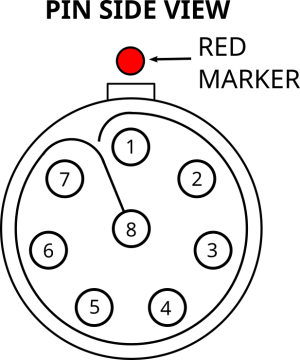
| Pin | Function | Connector color |
|---|---|---|
1 |
Sense Electrode Shield |
N/A |
2 |
Sense Electrode (S) |
White (stackable) |
3 |
Working Electrode 2 (WE2) |
Yellow |
4 |
Working Electrode (WE) |
Red |
5 |
Counter Electrode (CE) |
Black (stackable) |
6 |
Reference Electrode Shield |
N/A |
7 |
Reference Electrode |
Blue |
8 |
Working Electrode Shield |
N/A |
Connector housing |
Analog Ground (AGND) |
Green |
The S2 connector can be used to monitor a potential vs RE or versus S or used to measure the half-cell potential during a dual-EIS measurement
LED ring
The illuminated indicator ring is used to communicate the device state. The following table shows the meaning of the different states the indicator ring can have.
| State | Pattern |
|---|---|
Starting up or shutting down |
Breathing blue at 0.5 Hz |
Cell off |
Solid blue |
Cell on |
Breathing red at 1 Hz |
MethodSCRIPT paused |
Rotating white at 0.33 Hz |
Warning |
Blinking amber at 2.5 Hz |
Error |
3 short red flashes every second |
Additionally, the illuminated indicator ring behavior can be controlled from MethodSCRIPT using the “notify_led” command. The following table shows the different supported notify modes.
| Notify mode | Pattern |
|---|---|
Idle |
Solid blue |
Busy |
Solid red |
Notice |
Blinking white at 1 Hz |
Pass |
Blinking green at 1 Hz |
Fail |
Blinking red at 1 Hz |
Warning |
Blinking yellow at 1 Hz |
Error |
Blinking yellow at 2 Hz |
Auxiliary port pin-out
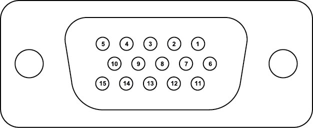
| Pin | Function |
|---|---|
1 |
GPIO 0 1 |
2 |
GPIO 3 1 |
3 |
auxiliary analog input -10 to +10 V, 18 bit, 1 MΩ input impedance |
4 |
I2C SCL (pulled up to 3.3 V via 2 kΩ resistors) |
5 |
I2C SDA (pulled up to 3.3 V via 2 kΩ resistors) |
6 |
GPIO 1 1 |
7 |
GPIO 4 1 |
8 |
i monitor given as -2 V / active current range |
9 |
5 V digital power line (max. 300 mA) |
10 |
digital ground |
11 |
GPIO 2 1 |
12 |
GPIO 5 1 |
13 |
E monitor (-12.5 to +12.5 V) |
14 |
analog ground |
15 |
auxiliary analog out (0 to 10 V at 16 bit) |
Connector housing |
digital ground |
1 Pulled up to 3.3V via 2.49kΩ, input/output
| Applying external power to pins on the AUX port when the Nexus is switched off can potentially damage the instrument. |