Getting Started
Recommended software tools
The following software tools are recommended:
-
PSTrace - software for Windows for use with EmStat4M
-
Tera Term - open-source terminal for direct serial communication
-
Notepad++ - free and simple source code editor to replace the default Windows Notepad
-
Visual Studio Code - free and open-source Integrated Development Environment (IDE) for use with our SDK’s for .NET
Connecting to the PC via USB-C or micro-USB
You can either connect the PC directly using the USB-C port on the EmStat4M module or you can use the micro-USB connection of the development board.
| Do not use the micro-USB and USB-C cables simultaneously. |
The micro-USB port on the development board is meant for programming the BT module, charging, or testing the UART lines to the EmStat4M.
When using the USB-C port on the EmStat4M module, the communication on the PC side is handled by the Windows CDC drivers. The micro-USB port works using an FTDI chip for USB to serial communication. With both USB ports a connection can be made via a serial virtual COM port to use a terminal program like Tera Term for example.
The following table shows the implications for connecting either to the micro-USB of the development board or the USB-C cable of the EmStat4M module.
Micro-USB cable to development board |
USB-C cable directly to EmStat4M |
|
Speed |
230.000 baud (default) allowing for +/- 700 datapoints/second |
Full-speed USB allowing for +/- 2500 datapoints/second |
Connecting to PSTrace |
Shows as “ES4Dev” |
Shows as “EmStat4 LR” or “EmStat4 HR” |
Drivers |
Works standard in Windows 7 to 11 without installation of special drivers |
Works out-of-the box in Windows 10 and 11, requires EmStat drivers to be installed (via PSTrace) in Windows 7 |
Other functions |
Allows for direct communication between PC and the Laird BT900 Bluetooth module |
Allows for automatic firmware updating of the EmStat4M module in PSTrace |
To communicate to the EmStat4M via the micro-USB port make sure all switches (1-4) of SW7 (ES_to_USB) are set to ON and for SW4 (BT_to_USB) and SW5 (BT_to_ES) all switches are set to OFF.
| PSTrace 5.9 does not support flow control: When communicating with PSTrace 5.9, make sure only to only set SW7 pin 3+4 to ON and pin 1+2 to OFF. |
Using the Real-Time Clock
Place CR1216 in BT1 battery-holder as backup supply for the S-3590A RTC (S-35390A REAL-TIME CLOCK - ablic.com).
The RTC can be accessed via MethodScript i2c commands. See https://www.palmsens.com/wp-content/uploads/2022/01/MethodSCRIPT-v1_3.pdf Chapter13.5 I2C example - Real time clock
Using the EEPROM
Non-Volatile data can be stored in the 32-Kbit I2C Serial EEPROM (24LC32AT). The EEPROM can be accessed via MethodSCRIPT I2C commands. See https://www.palmsens.com/wp-content/uploads/2022/01/MethodSCRIPT-v1_3.pdf Chapter 13.6 I2C example - EEPROM example
Using an Arduino MKR Zero
To access the EmStat4M from the Arduino MKR set all switches of SW6 to ON and all switches OFF for SW4, SW5, SW7.
| There’s no hardware-handshaking (CTS/RTS) between the Arduino MKR and the EmStat4M. |
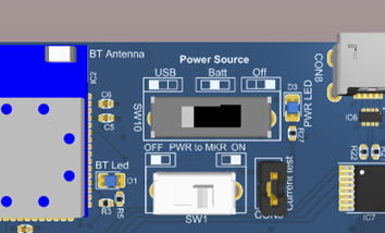
Powering the Development Board
The EmStat4M Development board can be powered from 3 sources selectable with SW10:
Powering from the micro-USB or USB-C port
When an EmStat4 HR is installed, the maximum current drawn from the USB port will exceed 500mA when using the 100 mA range. Use a Y-cable to split the total current into 2 USB ports or make sure the port can handle current up to 900mA.
| The EmStat4HR requires up to 900 mA in the 100 mA range. Make sure to use the USB Y-cable to ensure enough power can be drawn from the USB ports. |
Powering from a Lithium-Ion battery
The JST PH2 connector (CON10) is suitable for Adafruit batteries like https://www.adafruit.com/product/328 or https://www.adafruit.com/product/2011. It is recommended to use a battery capacity of 2000mAh or more.
The battery is charged when the Development board is connected via CON8 (Micro USB). The charge current is set to ~150mA, a 2000mAh battery may take 10 to 14 hours to be completely charged. The charge current can be changed by changing the value of R31.
See the datasheet of IC8 for detailed information:
Powering from an Arduino MKR board
| You can only power the EmStat4M Development board from an Arduino MKR when the development board is a version 1 or 2. The version of the board can be found printed on the top or the bottom side of the board: “ES Dev VX”. |
In case an Arduino MKR board is connected to the bottom side of the development board, all boards can be powered by a single USB connection to the Arduino.
For V1: This can be done by setting SW1 to 'PWR from MKR' and setting SW2 to 'OFF'. Now, the Arduino board can be connected via a micro-USB cable to the PC or other USB power source.
| Having SW2 in the 'ON' position AND SW1 in the 'PWR from MKR' position simultaneously when power is connected may damage the MKR and/or the board. |
For V2: This can be done by setting SW10 to 'MKR' and SW1 to 'OFF'. Now, the Arduino board can be connected via a micro-USB cable to the PC or other USB power source.
| Having SW10 in the 'MKR' position and SW1 in the 'ON' position simultaneously when power is connected may damage the MKR and/or the board. |
Heat dissipation when using EmStat4M HR
The EmStat4M HR is designed for higher currents and is protected against over-current and high temperature. To prevent entering these overload conditions make sure that the setup has good airflow When the EmStat4M is used in a closed environment (housing) forced air-cooling (fan) is strongly recommended.
| When using the maximum current range with an EmStat4M HR, proper heat dissipation around the heat sinks is essential. |
| MethodSCRIPT error 0x0032 will be thrown in case of an overload condition |
Connecting the cell (or sensor)
To do valid measurements on an electrochemical cell, the RE, WE and CE of the EmStat4M module and the Sense lead (for the EmStat4M HR) need to be connected.
| Make sure to always connect the Sense lead when using the EmStat4M HR. In most common situations, the Sense lead connects directly to the WE. |
There are multiple ways to connect a sensor or cell to the EmStat4M:
-
Using the LEMO connector on the EmStat4M module
-
Using the screw terminals on the development board
A small screwdriver is supplied for using the screw terminals. The SPE connector for use with Screen Printed Electrodes that have the common 2.54 mm pitch can be screwed in directly to the screw terminals.
| In case of using the SPE connector with an EmStat4M HR, make sure the Sense is also connected to the WE. This can be done by using a small wire and screwing it in together with the SPE connector. |