Getting Started with the EmStat Pico Module
On this page we will guide you through the setup and running your first measurements on the EmStat Pico module.
Prerequisites
In order to start development with the EmStat Pico module there needs to be a possibility to connect to it. We recommend soldering headers on the EmStat Pico module and using jumper wires to connect to other devices.
For USB communication a USB to UART converter is needed. Since the EmStat Pico has a logic level voltage of 3.3V the converter needs to work on that same level. In this guide we will be using the UMFT234XD-01 but other converters with 3.3V logic level will also work. When using the UMTF234XD converter install the FTDI VCP driver on your computer.
To communicate with the EmStat Pico module a serial terminal is needed on your machine. In this example Tera Term will be used. Next to that PSTrace will be used for making MethodSCRIPT and running a measurement.
Furthermore a breadboard with some extra electrical components will be used. The list of parts needed to follow this guide is given below.
Recommended parts list:
-
Through hole pin headers, 2.54mm pitch, 1 row (2x 9 pins, 2x 5 pins)
-
USB to UART converter, UMFT234XD-01
-
Male to male jumper wires (dupont)
-
Male to female jumper wires (dupont)
-
Breadboard
-
560 Ohm resistor
-
10K Ohm resistor
-
33nF ceramic capacitor
First connection
To make the connection of the computer with the EmStat Pico, the USB to UART converter needs to be connected to the EmStat Pico. The following table shows you which pins to connect between the converter and the module.
USB to UART Converter |
EmStat Pico Module |
5V |
5V (pin 27) |
GND |
GND (pin 28) |
TXD |
RX (pin 2) |
RXD |
TX (pin 3) |
RTS# |
Download (pin 4) |
CB0 |
Reset (pin 5) |
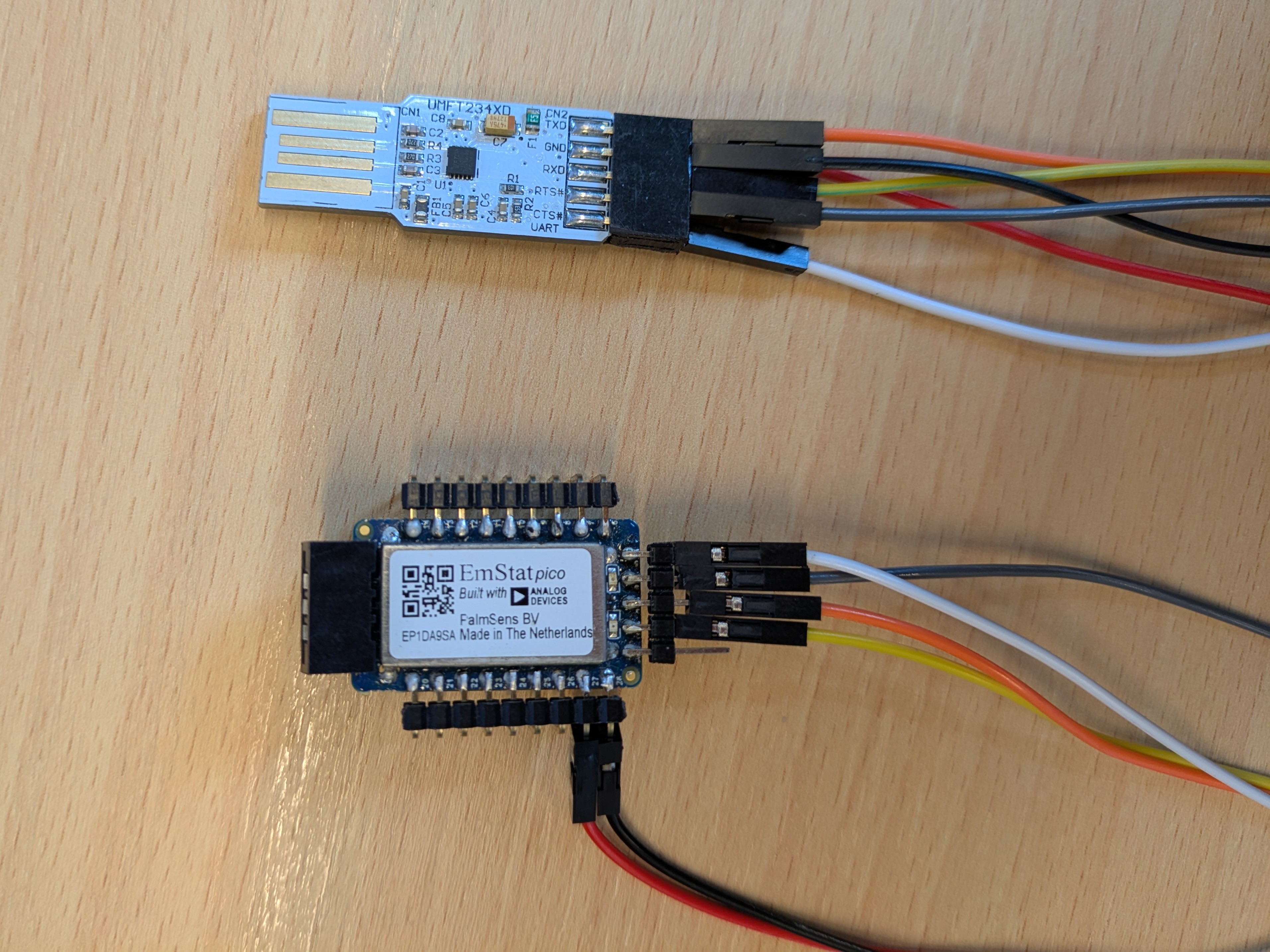
With the connections between the converter and the module in place the USB to UART converter can be plugged into a USB port of your computer. When the module gets power a blue light should turn on. A serial terminal program (Tera Term) can be opened and connected to the COM port of the converter. To correctly communicate with the module change the following settings:
Setting |
Value |
New line character |
LF |
Local echo |
on |
Baud rate |
230400 bps |
Number of data bits |
8 |
Number of stop bits |
1 |
Parity |
None |
Flow control |
Software (XON/XOFF) |
Now a 't' can be typed in the terminal followed by an enter/new line (this new line will often be denoted as '\n'). The response of the EmStat Pico should be to return its firmware version as following:
t
tespico1500#Mon dd yyyy hh:mm:ss (1)
R* (2)
| 1 | Here first the t is echoed by the Pico following its device name 'espico' and its firmware version '1500' (v1.5). After the hash symbol it will display the build date and time of the firmware. |
| 2 | The 'R' indicates the release version of the firmware and the '*\n' indicates the end of the message. |
More information about direct serial communication and the commands that can be used can be found on the communication protocol page.
Making MethodSCRIPT
To make it easy for ourselves we can let PSTrace generate the MethodSCRIPT we need for the technique that we want. Let us generate an EIS method as follows:
Open PSTrace and under connection select 'Virtual EmStat Pico'. Now Select 'Impedance Spectroscopy' from the list of techniques. The following settings will be applied to make a simple technique:
t equilibration |
3 s |
Scan type |
Default |
E dc |
0.0 V |
E ac |
0.01 V |
Frequency type |
Scan |
n frequencies |
39 = 9.5 / dec. |
Max. Frequency |
200000.0 Hz |
Min. Frequency |
20.0 Hz |
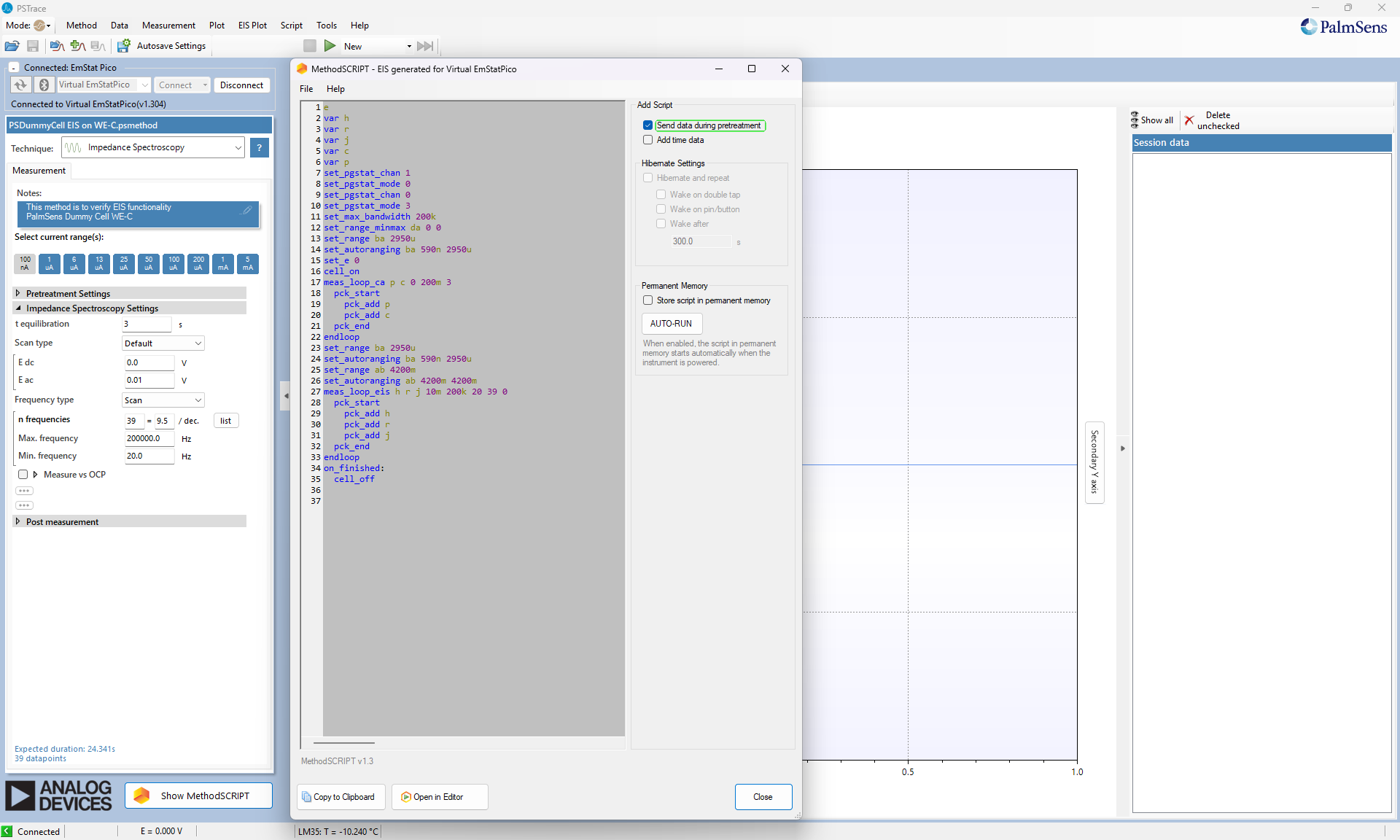
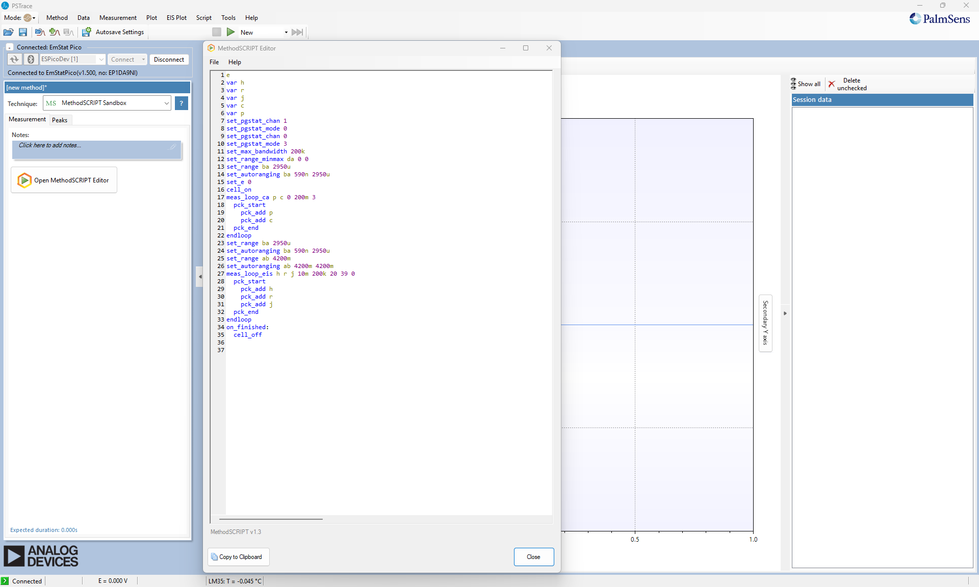
At the bottom the 'Show MethodSCRIPT' button will open a new window with the generated MethodSCRIPT for this technique. The screen that you will see is shown in the figure below.
Doing a measurement
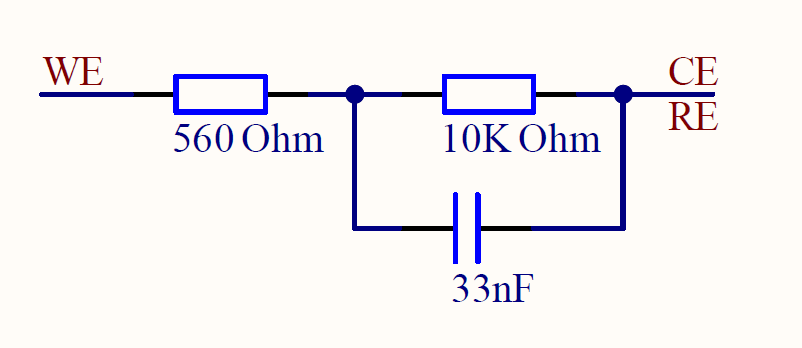
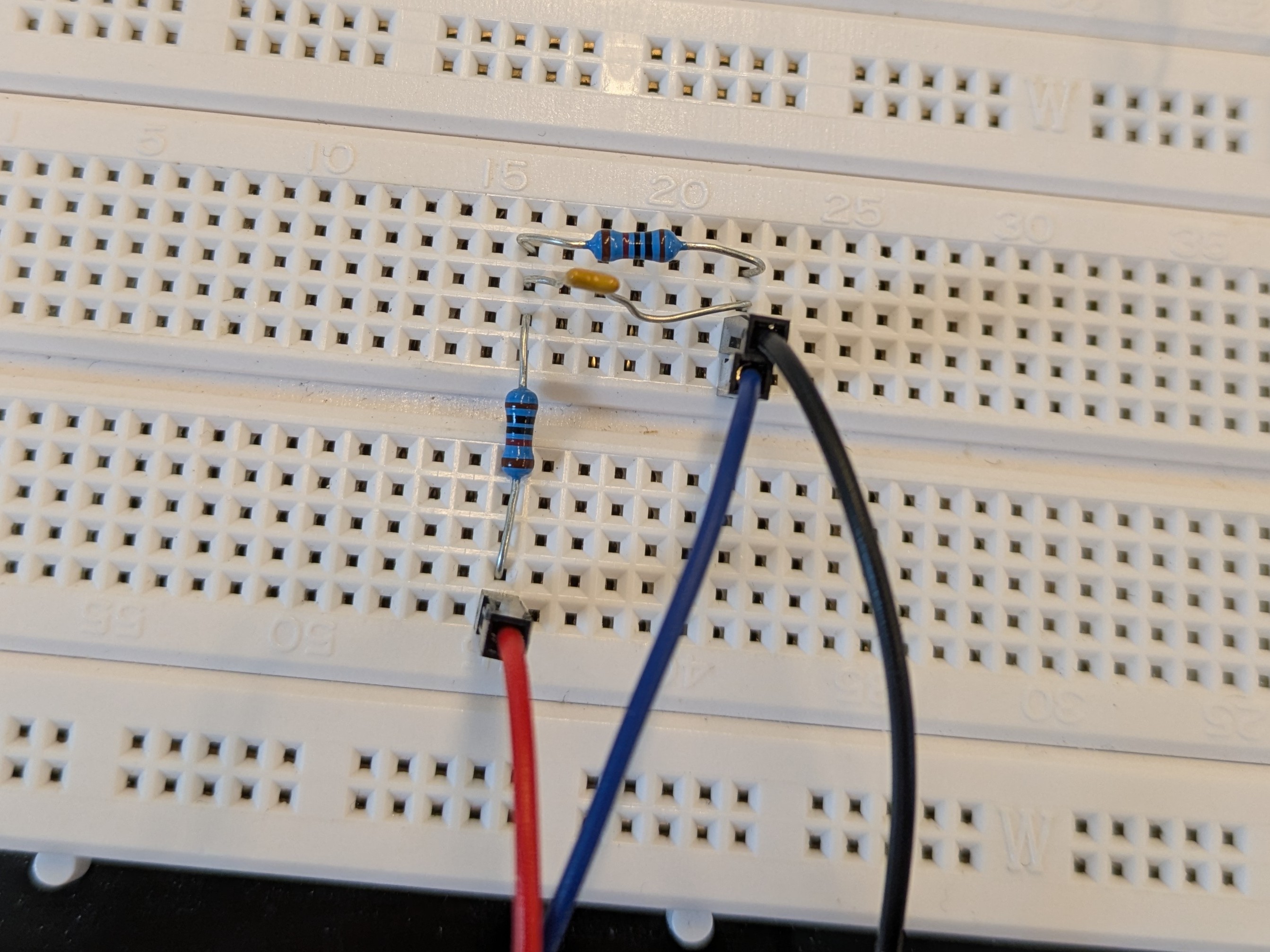
To setup the EmStat Pico module for this measurement, ch0 of the module needs to be connected to a measurement circuit. By connecting jumper wires to pin 18 (Counter Electrode, CE), pin 17 (Working Electrode, WE) and pin 16 (Reference Electrode, RE) a breadboard can be connected on which a Randles circuit can be built. The circuit diagram for this circuit is given below and how this would look like on a breadboard.
With the Randles circuit connected the MethodSCRIPT generated by PSTrace can be copied, including the two empty lines at the end, and pasted in the terminal of Tera Term. When the MethodSCRIPT is sent, the EmStat Pico directly starts with its measurements and should show its data packages in the terminal.
...
Pdc984E0DEu;cc8A0EED7m,10,287;cd7F85867m,10
Pdc9312D1Cu;cc8A1169Am,10,287;cd7F95D50m,10
*
The data packages are hard to read without any post processing. This could be done with a programming language of your choice as described in the MethodSCRIPT Examples section. But for now we are going to use PSTrace to plot the data.
Close Tera Term (or lose the connection to the COM port). In PSTrace under devices we are now going to disconnect from the virtual EmStat Pico and connect to the COM port of the EmStat Pico. The EIS method that we made just before should still be shown. Again we can click on the show MethodSCRIPT button. Now we click open in editor. This is the environment where we can execute our own MethodSCRIPT commands without using the terminal and directly see the data that comes out.
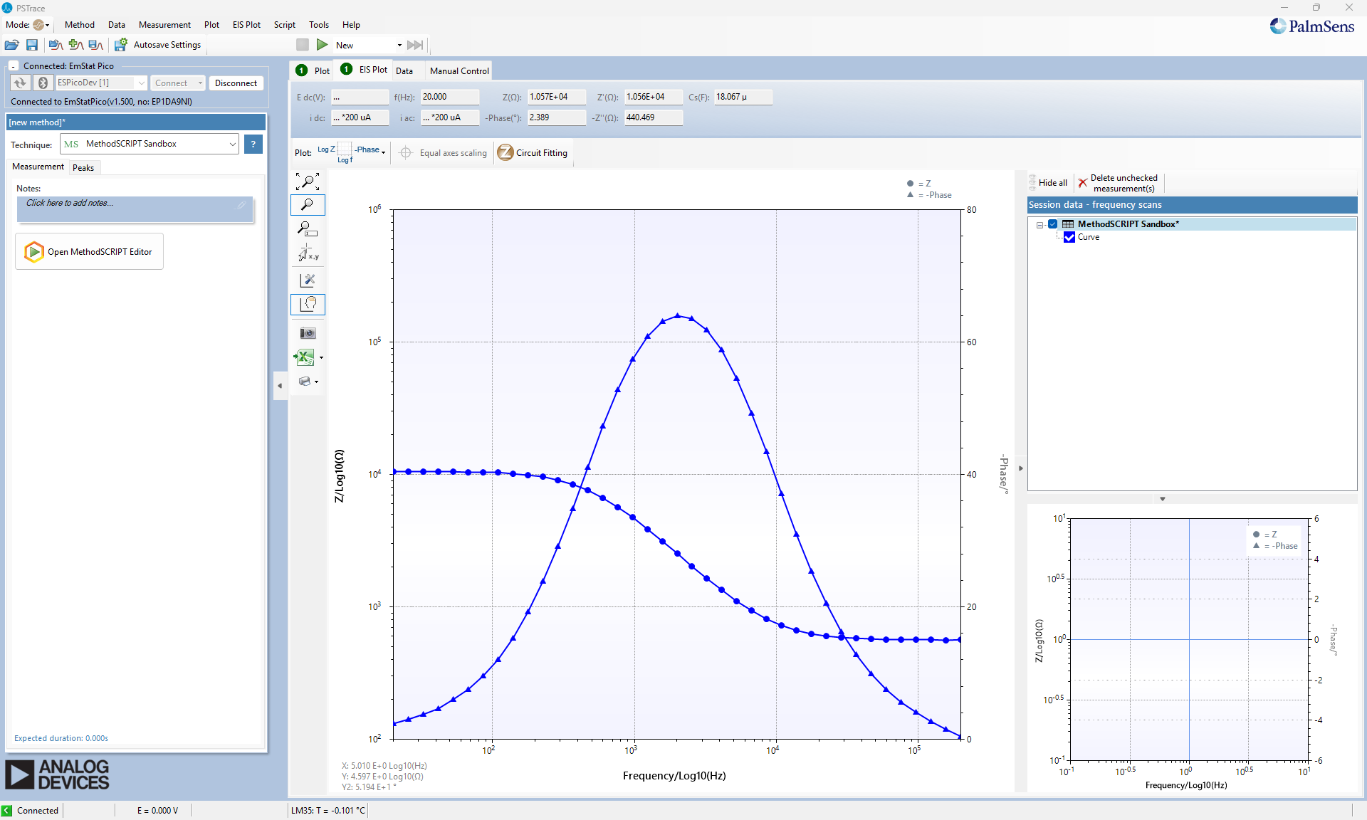
Close the MethodSCRIPT text editor and press the green play button. The EmStat Pico starts with the measurement and now the data that is generated can be seen on the left. The main graph that we see now does not show the data correctly but when clicking on the EIS plot we can see the data more clearly. Under plot options the bode plot can be selected and we see the data as shown below.
Continue developing
This getting started guide is a framework to start developing your own methods and setups with the EmStat Pico. By following these steps and changing it to your own measurement technique and cell setup you can quickly get familiar with using MethodSCRIPT on the EmStat Pico. For more examples look in the example section and for integrating the EmStat Pico with your program or programming language of choice look in the MethodSCRIPT examples section or at the SDKs.